Total System Efficiency: Condensing Boiler System Myth Busting
Written by David Grassl, PE Mechanical Engineer, Principal, Dynamic Consulting Engineers

There are many reasons why engineers have been led to believe that condensing boilers do not fit a design application. Most of these reasons are inaccurate.
Condensing boilers can be used in most applications where a standard, non-condensing boiler can be used. Some of these reasons may have been valid for older, non-condensing boiler systems, but for condensing boilers, many of these concerns have been eliminated.
Also, within the condensing boiler segment, there are a variety of technologies available. Some condensing boilers require more maintenance than othersor have specific piping, pumping, and flow requirements. High mass firetube condensing boilers have been developed to overcome many of these obstacles and can be piped in a variety of systems with success. Therefore, it is important to understand each boiler’s operating requirements, as well as total cost of ownership, when making a boiler selection.
MYTH #1 – WE NEED TO MAINTAIN 180°F HOT WATER SUPPLY FOR THE SYSTEM TO WORK
Prior to condensing boilers, it was common for systems to be designed with high hot water supply temperatures in the range of 180°F to 200°F. One of the main purposes of the high hot water temperature was to satisfy the hot water return temperature back to the boilers since a higher hot water supply temperature results in a higher hot water return temperature delivered back to the boiler. In non-condensing boilers, the hot water return temperature is critical, as the water temperature must always be maintained above the condensing temperature of the flue gases to protect the heat exchanger.
Like non-condensing boiler systems, in condensing boiler systems, a lower hot water supply temperature results in a lower hot water return temperature delivered back to the boiler. The difference with a condensing boiler is that hot water return temperature is the driving force behind condensing boiler efficiency. In condensing boilers, the goal is to generate as much condensation as possible because the heat exchanger is constructed of a corrosion resistant material such as stainless steel or aluminum specific to this application. In addition to the hot water return temperatures, coils can also be designed to satisfy the load based on varying hot water temperatures. Table 1 demonstrates this point by comparing a main heating coil, typically found in an air handling unit, selected to do the same duty for both 180°F and 140°F hot water supply temperatures with a respective temperature difference of 40°F to satisfy the total heating capacity required. In both cases, the coil provides the same output, in MBH, to the heat air with minor differences in coil characteristics.
Table 1: Comparison of two (2) heating coils selected at 180°F and 140°F hot water supply temperatures with the same system ΔT.
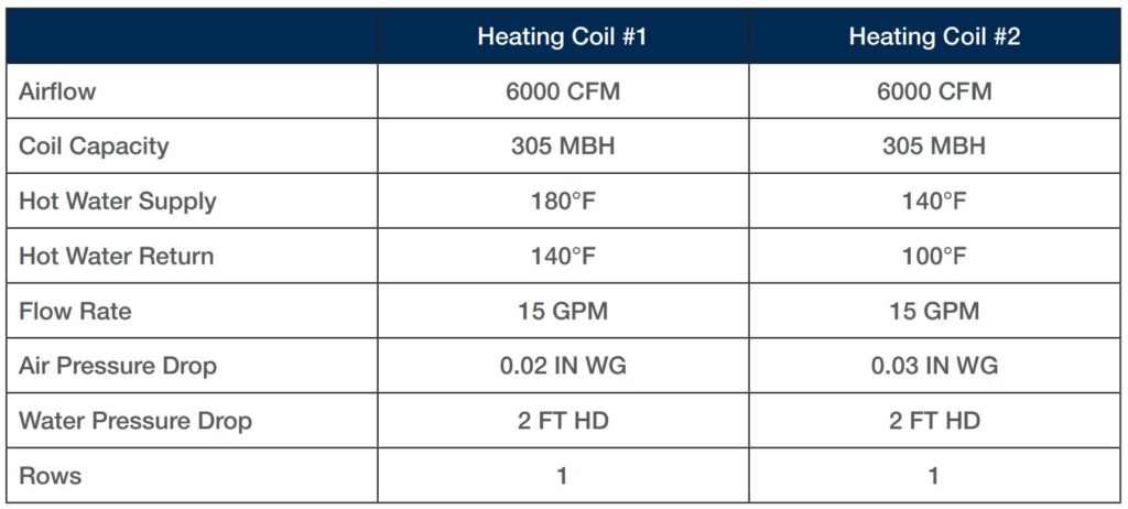
Take note of existing systems that were designed for 180°F hot water supply temperature. With an existing system, the designer is typically stuck with the existing coils sized per the original design. Despite this, a condensing boiler is still an option, but care must be taken to ensure the hot water supply temperature at any given time will meet the load conditions required. With all things being equal, lower hot water supply temperatures will require more heat- transfer surface area to meet the same load. This point is demonstrated in Table 1 as the coil selected for 140°F hot water supply temperature has more fi ns compared to the coil selected for 180°F hot water supply temperature. With that being said, many coils are oversized to some extent because upgrades to buildings have improved their envelope characteristics and leakage rates over time, so less heat output typically is needed. This means there is potentially the ability to operate the building the majority of the year at the reduced water temperatures or at the very least, be able to operate with more aggressive hot water reset strategies while improving system efficiency.
MYTH #2 – WE NEED TO MAINTAIN A 20°F SYSTEM ΔT
Myth #2 is similar to myth #1 in that older systems typically maintain a low ∆T in order to keep the hot water return temperature above condensing conditions. In condensing systems, temperature differentials of 30°F or higher can be designed to increase boiler efficiency by lowering the hot water return temperature back to the boiler. Increasing the temperature differential between the supply and return water has the added benefit of reducing the flow rate since the fl ow rate is related to the overall heat output of the coil. Therefore, the higher the ∆T, the lower the flow rate, which results in smaller pumps, less horsepower required to move the fluid, smaller piping, and other system benefits.
MYTH #3 – HOT WATER RESET DOESN’T WORK
Hot water reset involves resetting the hot water supply temperature based on outside air conditions. The theory behind resetting the hot water supply temperature is that as the outside air temperature increases from the design condition, the amount of heat required to satisfy the space load decreases. Similarly, as the space load decreases, it is also possible to heat the space with a hot water supply temperature less than the design condition, which uses less energy to heat the water to a lower set point.
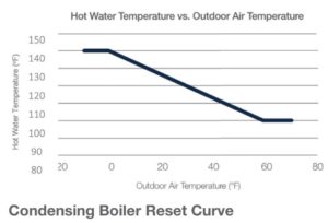
Hot water reset is a simple control strategy that has been used for many years on hot water systems with a lot of success. With condensing boilers, the hot water reset functionality based on outside air is generally built in, making this a relatively low- or no-cost item to implement within the system. Reset strategies have also been used on supply air and chilled water systems for years, so designers, operators, and contractors are aware of the design intent and goal of resetting system temperatures. The one item that should be understood regarding hot water reset is that there are conditions where resetting the hot water supply temperature will require additional flow to satisfy the load. In this scenario, hot water reset is less efficient as the additional pump energy required to move the fluid costs more than the energy benefits received from resetting the water temperature, so this condition should be avoided.
MYTH #4 – VARIABLE-FLOW-PRIMARY SYSTEMS ARE MORE COMPLEX
Hot water systems are generally known for using primary-secondary systems, which became the norm as noncondensing boilers cannot handle variable flow to maintain hot water return temperatures above condensing conditions. In primary-secondary systems, primary flow is maintained as a constant flow rate, which keeps the return water away from potentially creating a condensing opportunity for the flue gases.
As for the argument that variable-flow-primary systems are more complicated, there are many installations that demonstrate primary-secondary systems are just as complicated. For example, installations that have a check valve in the common pipe. The check valve typically is used as a post-design solution on a system that has difficulty supplying hot water to the system where the primary-loop, or boiler-loop, flow rate is less than the secondary loop, or distribution loop. This condition creates mixing and provides a hot water temperature less than that created by the boilers. It eliminates free, bi-directional flow in the common piping, which is the main objective of a primary-secondary system.
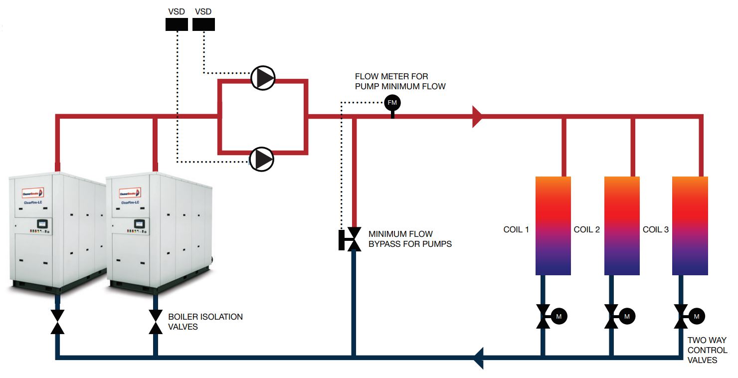
In actuality, variable-flow-primary systems are simpler than primary-secondary systems as variable-flow-primary systems only require one set of pumps to handle everything in the system. Also, there is no mixing due to two hydraulically separate pumping loops and less equipment is required, so there are fewer devices to control. In variable-flow-primary systems, there are three items that must be addressed for proper system operation. The first item is a flow meter that can measure the water flow rate to the distribution system. In many designs, this is common practice for measurement and verification or for owners who are interested in tracking the energy consumption, so it may already be part of the design. The second item is a minimum-flow bypass with a modulating two-way temperature control valve, which is the same control valve at all the heating coils in the system. These two items work in parallel with one another as the flow meter ensures minimum flow to the boilers and/or pumps is always maintained thus protecting the equipment. Many condensing boilers have very low- or no-minimum flow requirements, but verify this with the manufacturer as the lower the minimum flow, the less bypassing that will occur.
Once the minimum flow is determined, the control logic for the minimum-flow bypass is to modulate the two-way control valve to meet the minimum flow rate of either the boiler or pump, which bypasses the system and returns to the boilers and pumps as shown in Figure 1. The minimum-flow bypass concept is commonly used in today’s system designs and is very similar to three-way valves in constant volume systems that reduce flow rate through the coil when the space is at reduced capacity, thereby bypassing excess flow around the coil and maintaining a constant flow rate at the coil.
The third item that is required in a variable-flow-primary system is another two-way temperature control valve at each boiler when there are multiple boilers operating in parallel. This control valve is a two-position isolation control valve that remains closed when the boiler is off and opens when the boiler is on. Like the hot water reset controls that are built in to most condensing boilers, this is also typically a function that the boiler controls can perform, if desired by the designer. The purpose of the control valve is to prevent fl ow through the boiler when the boiler is off, which results in bypassing and mixing with reduced hot water supply temperatures. Based on these three items as described, there are no additional components required for a variable-fl ow-primary system. Similarly, all of these items are typically used in a system in some form already, either for coil control or measuring system fl ow, which limits the need to understand new control algorithms or special sequences.
Figure 1: Minimum-flow-bypass control logic in a variable-primary-flow system.
MYTH #5 – REVERSE RETURN HELPS BALANCING
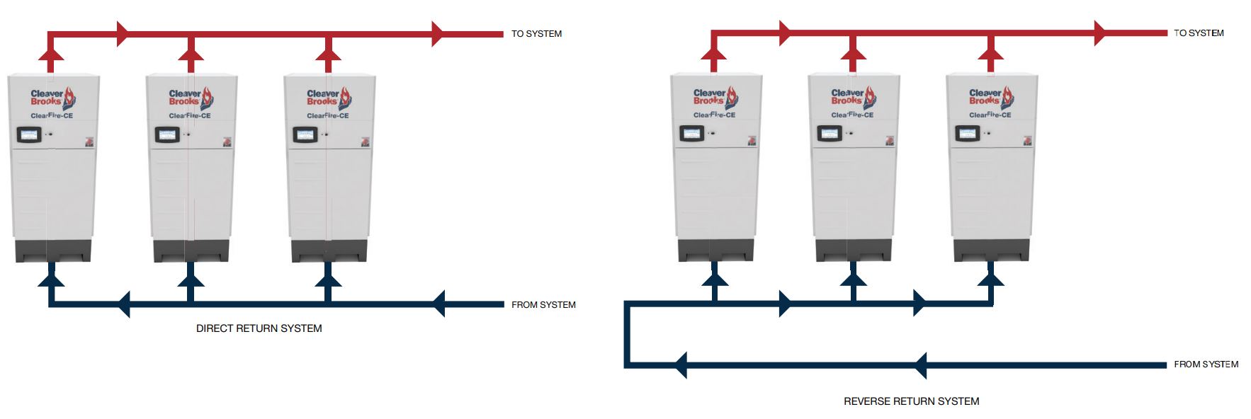
Piping distribution systems that deliver water to the system heating coils are designed using one of two strategies, either direct return or reverse return. Direct-return systems operate on the principle that the first coil in the distribution path closest to the boiler plant will also be the first coil to return the water to the boiler plant. Because of this, the piping distribution and corresponding pressure drop for this coil is typically much less than the last coil on the distribution network. As a result, if the flow rate to the coil is not properly balanced to have a pressure drop that effectively matches the other coil circuits, a large percentage of the system flow will take the path of least resistance, overflowing the closer coils and starving the coils at the end of the piping circuit.
Reverse return is a concept that evolved to solve the problem with direct-return systems. In a reverse-return configuration, the first coil to receive water from the central plant is designed to be the last coil to return water to the central plant. In theory, this equalizes the distance the water is pumped when distributed in the piping network and attempts to create a relatively equal pressure drop for each coil circuit. Figure 2 shows an example of direct return compared to a reverse-return system for the distribution system.
Figure 2: Direct-return compared to a reverse-return piping configuration.
The reverse-return piping configuration suggests that balancing can be significantly reduced or eliminated. Unfortunately, this does not work as well in theory as each coil circuit has varying pipe sizes with different flow rates and dissimilar water pressure drops at each coil. For a typical system consisting of multiple air-handling unit coils with high flow rates and large pipe sizes mixed with VAV box reheat coils and terminal unit heating coils with smaller pipe sizes, each circuit will be completely different so balancing will still be required. Therefore, reverse return doesn’t solve the issue it is designed to correct. Another disadvantage of a reverse-return piping system is that it takes the designer twice as long to design since both loops are different and must be sized based on the flow in the pipe at any given point in the system.
One negative that is commonly cited for both systems is their limited expansion. Depending on the method of pipe sizing recommended by the designer, these systems can have no or very little capacity for expansion. The truth is the sizing of pipes dictates the expansion capacity, not the fact that a direct- or reverse-return piping configuration is used. An additional argument that is typically made about reverse return is that there are conditions where reverse return is no more difficult to do from a piping layout. For example, as shown in Figure 3, a building has a piping shaft in the middle of the building and piping can be routed in a reverse return around the floor. This configuration would be the only potentially recommended condition to use reverse return on the distribution piping as no additional piping is required. Despite this, it still takes twice the time to size all the piping. The piping circuits will not be equivalent since all the coils and flow rates are not the same, and only the floor will be reverse return unless a third riser pipe is used in the shaft to create a complete reverse return system, which increases first cost. Regardless of the method used, it is important to note that balancing will always be required to some extent.
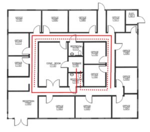 Figure 3: Reverse-return piping configuration on a floor where reverse return is relatively simple to design compared to direct return.
One time where reverse return could potentially pay off is when the equipment, flow rates, and pipe sizes are exactly the same, like in a boiler plant where there are multiple, similar-sized units. However, under this condition, the piping typically is much larger than in the distribution system, and the relative relationship of this equipment is so close that the equivalent length between individual devices is negligible. So, reverse return still doesn’t provide the value and would only be recommended if it can be done without adding pipe length or additional design time.
MYTH #6 – HOT WATER SUPPLY TEMPERATURE IS IMPORTANT FOR EFFICIENCY IN CONDENSING BOILERS
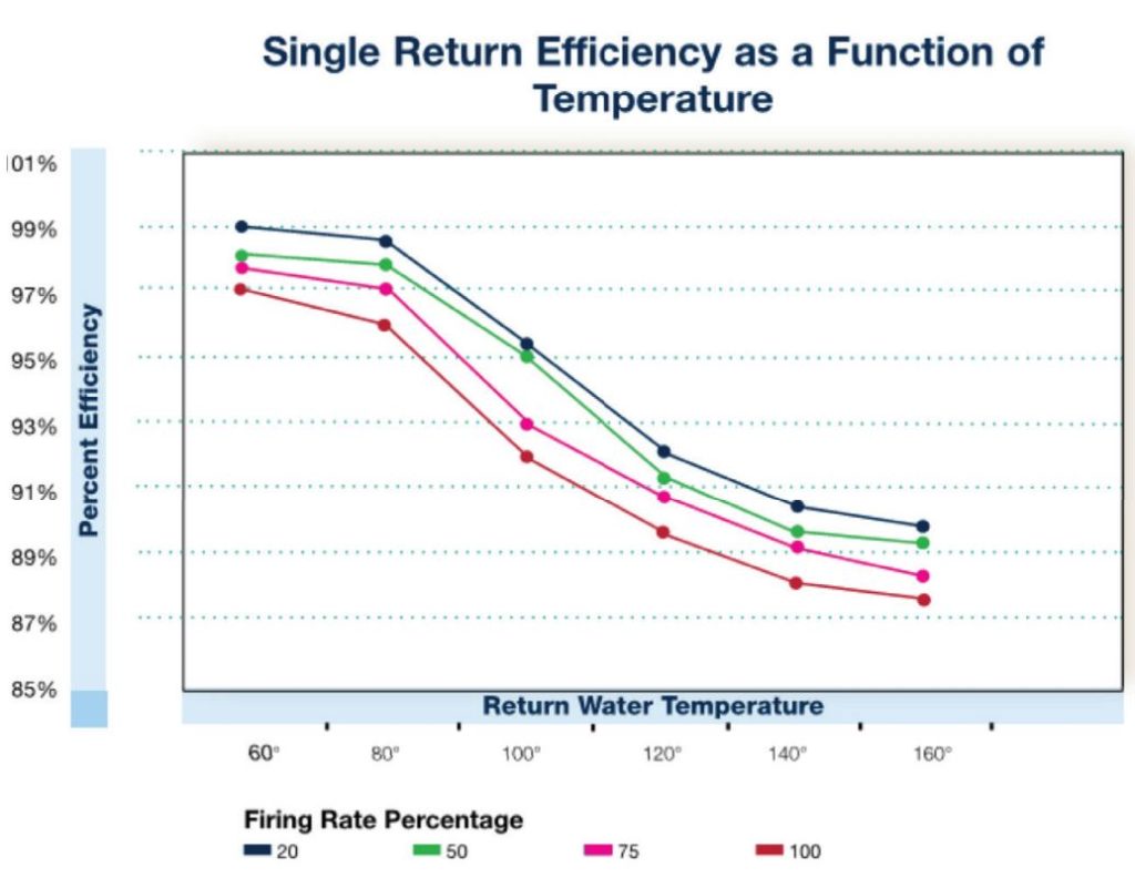
Hot water supply temperature is part of the equation in defining heating coil sizing, but it is not the defining point of determining a boiler’s efficiency. As referenced previously, boiler efficiency is dictated by the hot water return temperature since the amount of condensation that occurs in the heat exchanger depends on the temperature of the water compared to the flue gas temperature. Hot water supply temperature will almost always be above the condensing point of the flue gases, whereas the return water is the fluid that comes in first contact with the flue gases, cooling them to below the flue gas dew point, causing condensing and recovery of the latent heat from the moisture in the flue gas, which creates the efficiency gains as shown in Figure 4. Furthermore, Figure 5 proves that hot water supply temperatures do not dictate efficiency, as hot water supply temperatures are nowhere to be seen on the efficiency chart as hot water return temperatures determine efficiency based on boiler fi ring rates, demonstrating the lower the return water temperature, the higher the efficiency that can be realized by the system
Figure 4: The hot water return temperature to a condensing boiler dictates boiler efficiency as the water is the first contact point with the flue gases and more condensation occurs with lower water temperatures.
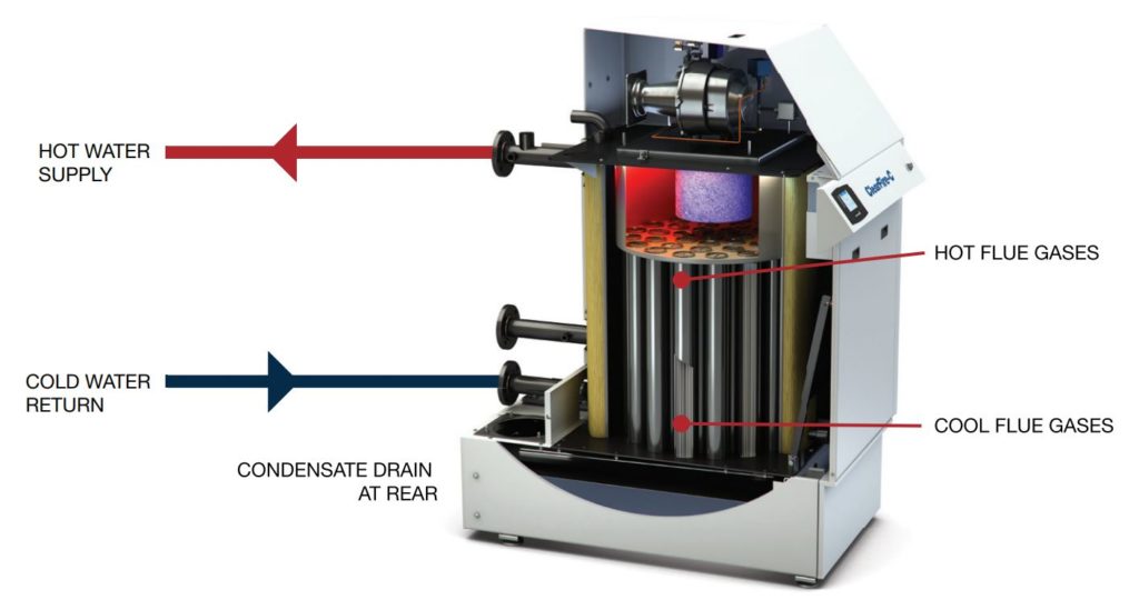
Figure 5: Boiler efficiency as a function of hot water return temperature.
MYTH #7 – CONDENSING BOILERS ARE MORE DIFFICULT TO SERVICE AND REQUIRE MORE FREQUENT SERVICE
Condensing boilers do not require any more service or maintenance compared to a standard boiler and heat exchanger. A condensing boiler consists of a stainless steel or aluminum heat exchanger that provides more resistance to changing water temperatures as compared to a standard, non-condensing boiler, where the operating temperatures, especially the return water temperature, are extremely important. In theory, although it is not recommended, less care could be provided to a condensing boiler due to its overall robustness. Due to its construction, a condensing boiler will last longer than a non-condensing boiler. If proper water chemistry and maintenance is performed, some condensing boilers are built to last longer than a non-condensing boiler.
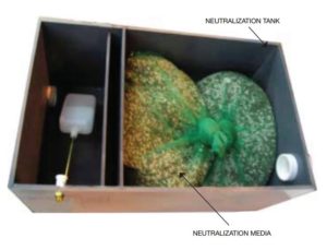 One area that does require more attention in a condensing boiler is the condensate drain. It needs to be checked to ensure the there is enough neutralization media for the capacity of the boiler. The neutralization kit is an acid neutralizer that increases the pH of the condensate to a neutral condition prior to discharging to the drain. When the media has expired, replacement is necessary – a task that can be completed in less than five minutes.
Figure 6: Example of a condensate neutralization media.
There are most likely more myths that exist for condensing boiler systems, but as explained, condensing boilers are not more difficult to design, install, or service compared to non-condensing boilers. In fact, the opposite is true for high-mass condensing boilers, which are generally more robust and require less attention. Systems can be designed for virtually any hot water temperature and ∆T provided a coil can be sized to provide the appropriate output at acceptable air- and water-pressure drops to maintain system efficiency. Similarly, hot water reset drives down hot water return temperatures, which is the main driver in system efficiency as more flue gases are allowed to condense with lower hot water return temperatures. Finally, variable-flow-primary systems with direct return should be considered the new paradigm since their system design is more straightforward and shortens design time.
Source: Cleaver-Brooks