Hydrodynamic Seals in the Pulp & Paper Industry
Written by Michael W. Day, ITT Gould Pumps, Copyright 1995, TAPPI, Technology Park/Atlantic GA 30348-5113
ITT Goulds Pumps determines hydrodynamic (or dynamic) sealing for pump stuffing box sealing is a successful alternative to other pump stuffing box sealing methods
Abstract
The Pulp and Paper Industry has increasingly utilized hydrodynamic seals — also known as dynamic seals — for stuffing box sealing since 1985 and forward. This paper reviews the fundamentals of dynamic seals including terminology, theory of operation, application considerations, typical services, and limitations.
Benefits derived from the use of dynamic seals are outlined. When used within established guidelines excellent performance can be obtained from dynamic seals when compared to packing or mechanical seals.
Introduction
Hydrodynamic seals have been used for over 50 years but little has been published about the design principles and the application criteria, which should be employed when this configuration is used. Early designs were used in slurry pump applications with mixed success primarily due to the lack of full understanding of the sealing capabilities of this design. Today, hydrodynamic seals are in use on slurry pumps, ANSI pumps, stock pumps, and axial flow designs among other.
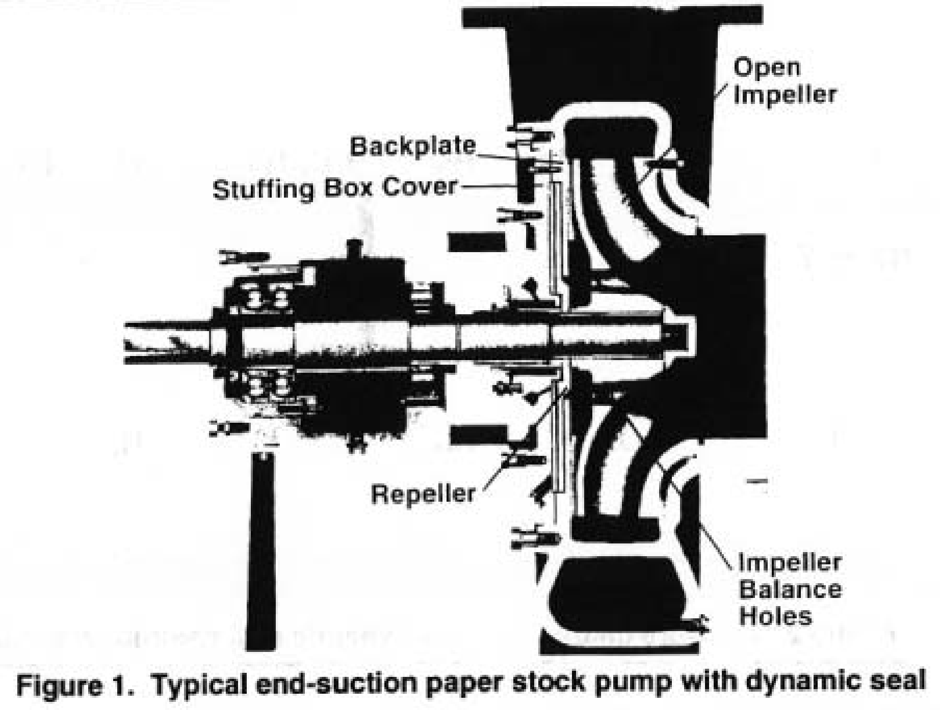
First, let us introduce some of the terminology appropriate to centrifugal pumps and hydrodynamic seals (Figure 1).
Pump Casing: Same casing as used for conventional centrifugal pumps.
Pump Impeller: Normally the standard impeller used with centrifugal pump but may be modified to include impeller balance holes if they are not standard. Balance holes are needed to additionally reduce the pressure behind the impeller in the stuffing box. On suction lift services balance holes are not required.
Repeller (Expeller): Secondary impeller between impeller and stuffing box. May be more than one repeller. Will reduce pressure in stuffing box. Repeller may be friction drive or key driven.
Backplate: Confines the repeller to facilitate high pressure gradients.
Stuffing Box Cover: Performs traditional function of pressure boundary and contains chamber for secondary sealing along the shaft especially in the shut down condition.
Secondary Seal: Acts to seal pumpage from atmosphere when unit is shut down and static suction head pressurizes the stuffing box. The secondary seal may be packing (self lubricating), lip seal designs, or diaphragm (flapper style).
Theory of Operation
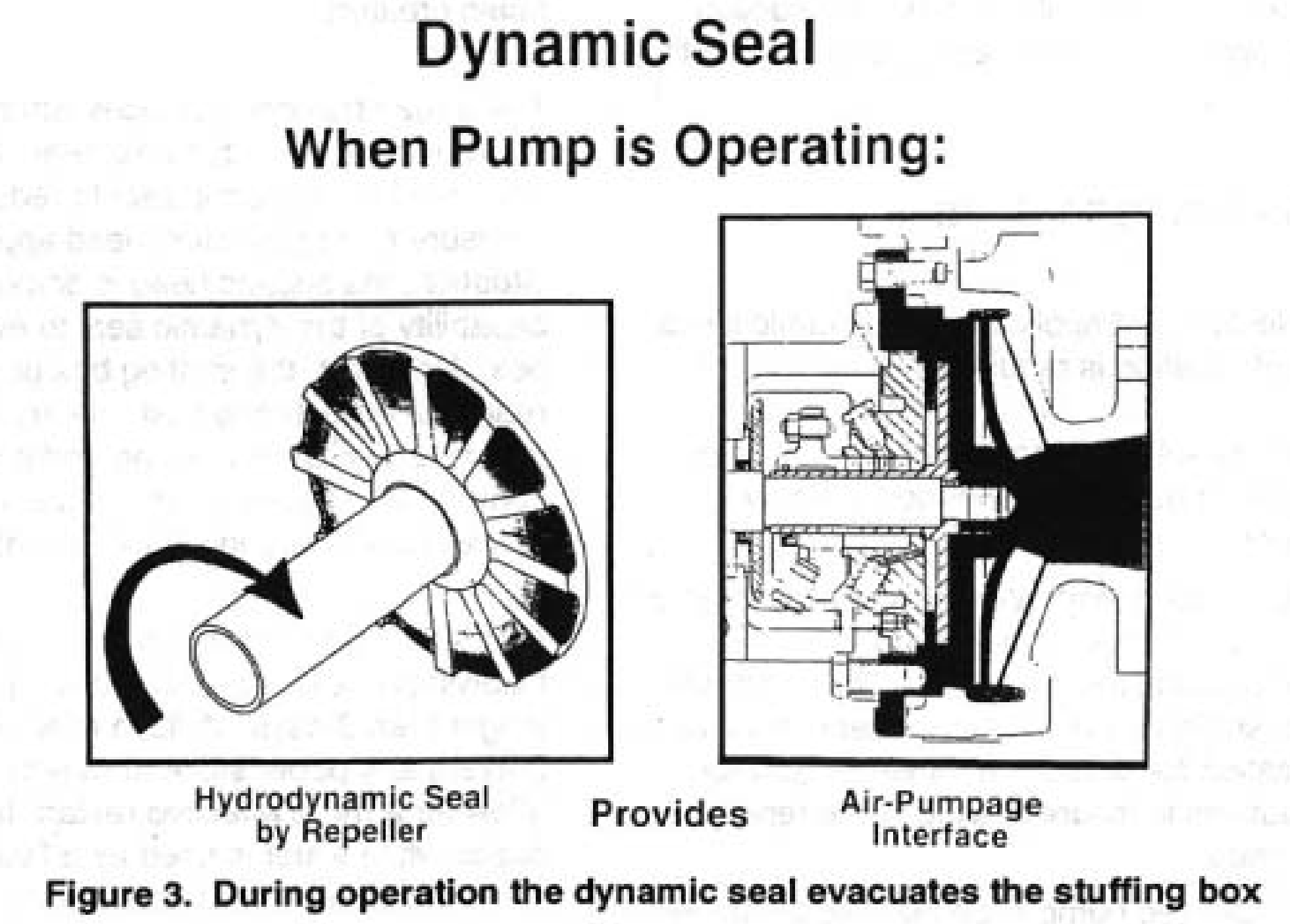
The repeller functions like an impeller upon startup and pups liquid from the stuffing box. This action allows outside air to follow the pumped fluid through the stuffing box the repair chamber where an air-liquid interface from at some point on the repeller. The stuffing box thus keeps clear of the pumped liquid. When the pump is shut down, a diaphragm secondary seal prevents liquid from escaping from the suffing box chamber.
The major advantage of the dynamic seal design is the repeller does the sealing when the pump is operating. The secondary seal does not run in the pumpage during operation thus is not subjected to the degrading effects of the pumpage. External flush water is not required for most applications. The basic benefits of the hydrodynamic sealing mechanism results in elimination or reduction of external seal water requirements, elimination of leakage, fluid contamination, and reduction of wear on the pump and sealing components during operation.
To realize the effective use of the hydrodynamic seal for centrifugal pumps, one major aspect must be the full understanding of the stuffing box pressure for the pump involved. Analytical techniques can permit reasonable prediction of stuffing box pressure. This becomes the pressure against which the dynamic seal must operate. The best method to establish stuffing box pressure involves actual laboratory testing under varying suction conditions throughout the operating range of the centrifugal pump curve from zero to maximum flow. Effects of operating parameters such as increased impeller clearance or the addition of impeller balance holes must be accurately determined to permit proper application; both on new equipment and the retrofit of existing equipment.
Hydrodynamic Seal: Pressure Distribution
Figure 2 portrays the pressure distribution in a hydrodynamically sealed centrifugal pump. Beginning at the pump suction, the section pressure is represented by Hs. The pressure generated with the impeller is designated Hd. Therefore, the volute pressure is equal to Hsd. Depending upon the pump design (impeller specific speed and/or casing configuration), the typical range of the volute pressure will be 75-90 percent of the discharge pressure. The pressure drop behind the impeller will vary depending upon configuration of the impeller. In the example shown, pumpout vanes were utilized which will reduce the pressure from Hsd at the impeller periphery, to Hss
Dynamic seal are, in fact, a pump. Power is consumed when performing the sealing function. Ranges for the kW required by dynamic seals be from 0.37 kW for small ANSI pumps to 3.7 kW in the largest paper stock pumps. The kW consumed by dynamic seals will range from 1 to 2.5 percent of the kW required by the pump.
Sealing head capability is usually defined as the static suction head which the unit can seal against during operation. For a fixed diameter repeller the suction head sealing capability will vary approximately with the square of the RPM.
Application Considerations
For proper selection and application of dynamic seals, the following information is required:
- Liquid: Percent solids, viscosity, and temperature fluid characteristics needed to verify suitability.
- Static Suction Head: What is the positive liquid level above the pump during normal, maximum, and minimum operating condition? It is possible to use a dynamic seal on vacuum application (or suction lift) however additional precautions to insure sealing at the repeller are necessary.
- RPM: Desired pump speed should be known so suction sealing head and kW requirements can be clearly identified. Variable speed applications should be reviewed at the minimum expected RPM.
- Material of Construction: Suitability for the liquid from a corrosion and wear standpoint are needed especially since dynamic seals are often applied on abrasive services.
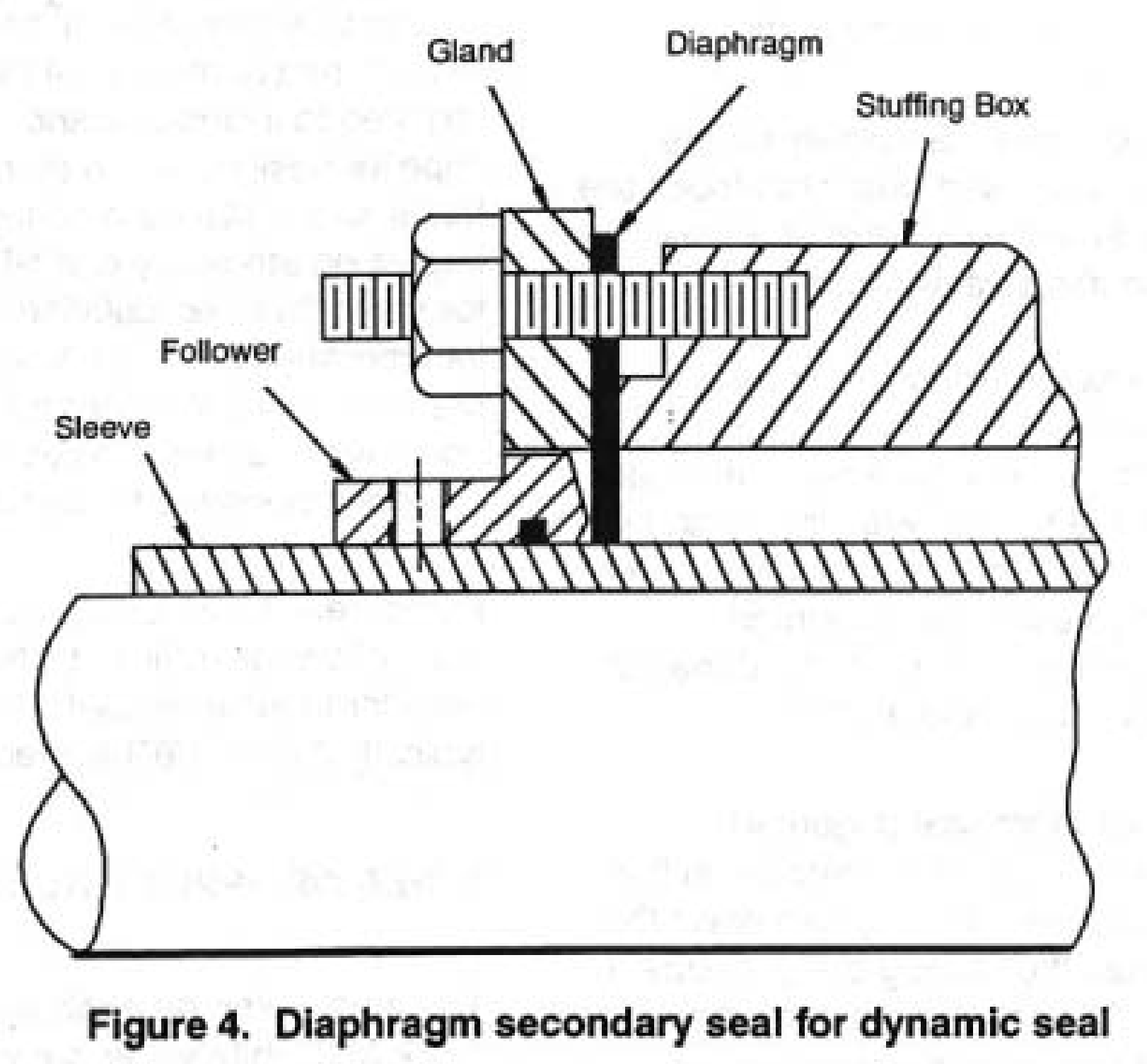
The type of secondary seal may depend on the application or the experience of the maintenance personnel. Often flexible graphic packing is used as maintenance personnel are familiar with its use and it is compatible with existing non dynamic seal units. The most common secondary seal is the diaphragm (flapper) design. The design is normally Bruna but EPDM may be used when the liquid dictates.
The operation of the diaphragm seal (Figure 4) depends on the repeller to reduce the pressure in the stuffing box below atmosphere. During shut down the static suction head causes the stuffing box pressure to be above atmosphere. The pressure pushes the diaphragm against the follower and a static seal is created. When the pump starts up the stuffing box is evacuated and the pressure reduced to a slight vacuum. This causes the diaphragm to deflect slightly and move away from the follower. Thus during operation, there is no rubbing contact of the diaphragm and follower. Thus during operation, there is no rubbing contact of the diaphragm and follower. When the pump shuts down, the pressure is restored. in the stuffing box, and the static seal is again created.
There may be circumstances when a flush is appropriate for the dynamic seal. Some users have employed the dynamic seal to reduce the stuffing box pressure on high suction head applications. In this situation, the suction head is above the sealing capability of the dynamic seal to evacuate the stuffing box. However, the stuffing box pressure is significantly reduced. An external flush at very low pressure and low flow rate increases packing and shaft sleeve life when compared to packing flush at plant water pressures of typically 350-520 kPa (50-75 psig).
Another situation in which flush may be appropriate is following an extended shut down period, typically longer than 3 days. A flush injected prior to restart will prevent any paper stock from remaining dewatered and allow for a more effective restart. In both of the above cases while water is used as a flush, it is either as an intermittent need or at significantly reduced amounts compared to conventional packed stuffing boxes.
To assist in reduction of the stuffing box pressure and extend the capabilities of the dynamic seal, it is typically required to include balance holes on the impeller. For impeller designs which do not incorporate balance holes as the standard configuration there will be an impact on efficiency and NPSHR. Balance holes allow for some fluid recirculation, consuming kW. This is incorporated into the kW requirements of the dynamic seal selection. An increase in NPSHR of up to 20 percent can occur when balance holes are added to an impeller not originally designed for use with balance holes.
Pump designs which utilize axial impeller adjustments must allow for sufficient internal axial clearance of the impeller to achieve useful life of the impeller. This is typically 3 mm (1/8″) movement for stock pump designs.
Types of Applications
The most common application for dynamic seals are on stock and white water pumps. Consistencies up to 6 percent can be handled without flush with new designs of dynamic seals(2). Recycle plant operations have been frequent candidates for dynamic seal applications. The reasons include high water cost when municipal water is the source, minimal maintenance staff personnel, and limited skills especially during initial plant operating periods.
Other application areas have included weak black liquor services, lime mud, and white liquor slurry pump applications, and remote location pumps, which see little attention.
Application to avoid the use of dynamic seals include:
- Medium to high solids (25 percent) black liquor.
- Liquids near the boiling point.
- Severe corrosive products, i.e., acids.
- Liquids which crystalize when exposed to air.
- Toxic or carcinogenic liquids, which mandate mechanical seals or sealless designs.
Limitations which need to be examined for each application include:
- Sealing head
- Repeller kW requirements
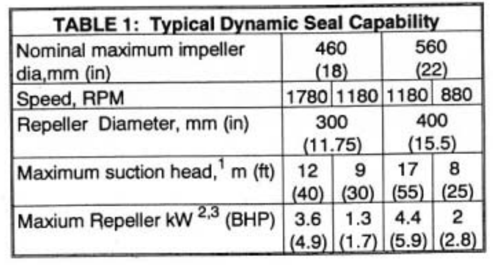
1. Above atmospheric
2. kW shown is based on 1.0 sp gr. Actual kW will vary with sp gr as does pump kW
3. Assumes full solid body rotation of liquid in repeller
A table such as Table 1 provides the necessary information for applying dynamic seals. The maximum suction head limits are shown which insure the stuffing box will be evacuated of the pumpage. The additional kW consumed by the repeller configuration is given to insure proper motor sizing. The increase in kW when using dynamic seals will typically be in the range of 1-2.5 percent of the total pump kW. A simple economic comparison of kW cost vs stuffing box water cost will assist in the evaluation of dynamic seal units(3).
Factors to Consider When Evaluating Dynamic Seals
- Packing replacement in conventional packed stuffing boxes.
- Periodic shaft sleeve replacement with conventional external flushed packed boxes.
- Safety and Housekeeping Elimination of seal flush water sprays and overflows improve the appearance of an installation and enhance the safety as part of the area involved.
- Materials of Construction Virgin fiber application will be low wear but 316SS is normally required for corrosion reasons. Recycle fiber (i.e., OCC with filler material and debris) can be high wear in repeller area due to concentration of filler material and abrasive debris. Minimum of 316SS is recommended.
- Flush provision in dynamic seal chamber, not in stuffing box area to allow for shut down periods (only intermittent flush is necessary).
- Drain provision for extended downtime situations.
- Mill water limitation. Limited quantities available perhaps due to mill restriction or cost. Poor water quality that is not suitable for packing flush. Limited mill water pressure to stuffing box.
Summary
The intent of this paper has been to acquaint users with some of the basic aspects of the hydrodynamic (or dynamic) sealing method for pump stuffing box sealing. It represents an alternative to the conventional packed stuffing box and mechanical seals. A basic description of the operational theory of dynamic seals has been provided to help understand the concept and limitations of this approach.
The many facets of application considerations to include sealing head limitation, kW requirements, secondary sealing mechanisms, and materials of construction are noted to illustrate the proper way to address stuffing box sealing, not just dynamic seals.
The foremost advantage of the dynamic seal is the elimination or significant reduction of external water for stuffing box flush and this benefit can carry across many functional areas within a mill environment.
Successful installations range from individual stock pump application in pulp mills to entire OCC recycle plants to de-ink facilities including flotation cell units to the chemical recovery area of a mill.
In short, the dynamic seal has taken its place as a successful alternative to other pump stuffing box sealing methods.
Source: ITT Goulds Pumps
Literature Cited
- Day, Michael, “Hydrodynamic Sealing of Centrifugal Pumps – Keys to Success”, World Pumps January 1995., Vol 340:39-41 (1995).
- Roll, D.R. and Wilson, G., U.S. Pat # 5,344,163 (Sept. 6, 1994)
- Cerza, Robert, “Dynamic Seals: Pump Protection with a Payoff”, Plant Engineering, June 23, 1988.