
Changes in Pump Vibration Levels Caused by the Misalignment of Different Style Couplings
Written by Jerome Lorenc, ITT Gould Pumps and PRO Services
ITT Goulds Pumps concludes the misalignment of metal couplings are less problematic than elastomeric couplings after pump vibration test
Written by: Jerome A. Lorenc, Instrumentation Engineer, Goulds Pumps, Inc.
Summary
Unacceptable pump vibrations are sometimes caused by the misalignment of the motor to the pump. Pump vibrations increases due to misalignment is dependent on the amount of misalignment and the type of coupling used.
The results and conclusions are reported of a test program that studied the effects that increasing amounts of parallel misalignment had upon pump vibration levels using different style couplings. The test setup used during the program and the test procedure followed to assure equal testing conditions for all the couplings are described. A total of nine different style couplings were tested.
One metal coupling was able to withstand a large amount of misalignment without causing a significant increase in the pump vibration level. Couplings using an elastomeric type insert tend not to increase the pump vibration levels when misaligned but do so at the cost of their useful life. Unbalance appears to be more of a problem with elastomeric couplings than with metal type couplings.
Introduction
Motor to pump alignment has always been a topic of interest to pump users, especially when vibration problems occur with a pump installation. Excessive pump or motor vibrations cause bearing failures, pipe breakage, cracked foundations and low meantime between failures (MTBF) of pump or motor parts. One variable in those discussions is the different types of couplings used. How much misalignment can a certain type of coupling withstand without degrading its performance or inducing unacceptable pump and/or motor vibrations? There have been pump vibration problems which appeared to be induced by the pump but, upon investigation, excessive misalignment or coupling unbalance were identified as the cause.
There are other causes of high vibration levels on a pump. But among the most common are unbalance of the impeller or coupling and misalignment between the motor and pump. Pump vibration levels due to misalignment can be affected by the size of the pump, the rigidity of the pump’s bearings and bearing housing, the design of the pump/motor baseplate, the amount of misalignment and the style of coupling used. Among the aforementioned that affect pump vibration, the easiest and simplest to change is the balance of the coupling and the alignment of the coupling. Knowing the relationship between pump vibration level changes and the degree of misalignment on different style coupling is a benefit to the pump user.
A test program was undertaken to study the changes in the pump vibration levels due to increasing amounts of motor-to-pump misalignment when using different style couplings. This report presents the equipment used, test procedure followed, results obtained, a discussion about the results and the author’s conclusions.
This test program was not intended to determine and recommend the coupling which could withstand the most misalignment without adversely affecting the pump vibration level. To select such a coupling would not always be the best approach to solve a pump vibration problem. Industry presently has good design, installation and maintenance practices for piping, bedplates, pumps and motors. These practices must be followed to assure the best motor/pump setup possible to minimize misalignment and unbalanced induced vibrations.
Equipment Setup
 An ANSI style 2×3-10 pump with a maximum diameter impeller was selected for this test program. A 100HP, 3560 RPM, 365 TS frame induction motor was chosen as the driver. The motor was mounted on an adjustable motor base. The motor base was mounted on the pump/motor baseplate so that only motor movement perpendicular to the pump shaft axis could occur.
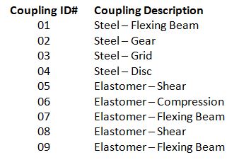
It would be prohibitive to test each style coupling by each manufacturers. Therefore, nine different couplings were chosen by their type, style, material of construction and use as pump-to-motor couplings. The couplings were sized to ensure they were loaded to between 50 to 100 percent of their published maximum continuous load carrying capacity — see list above.
A dial indicator mounted on the adjustable motor base was used to measure the amount of parallel misalignment.
Test Procedure
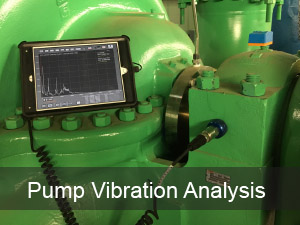
The pump, motor and baseplate were set up (Figure 1) on a closed loop tank facility. Special attention was given to assure proper installation of the baseplate, pump and motor. Once installed, it was not altered throughout this test program. The motor to pump alignment was performed using the rim and face alignment method [1]. Parallel and angular misalignment were reduced to less than 0.003 in total indicated runout (TIR). This alignment procedure was performed before each coupling was tested.
The motor was started and the pump was adjusted to its best efficiency point (BEP). The BEP condition for the ANSI 2×3-10 pump is 425 gallons per minute (GPM), 400 ft of head an 65HP. The pump was allowed to run for a minimum of 10 minutes before any test data was taken.
The overall (unfiltered) vibration level in inches per second peak (ips-P) was measured with a vibration analyzer. A vibration amplitude versus frequency (0-500 Hz) spectrum was also taken with the analyzer. All vibration data was taken on the thrust end of the bearing frame in the horizontal direction. The motor was incrementally misaligned using the adjustable baseplate. The amount of misalignment, overall vibration level and spectrum plot were recorded at each increment of misalignment.
Results
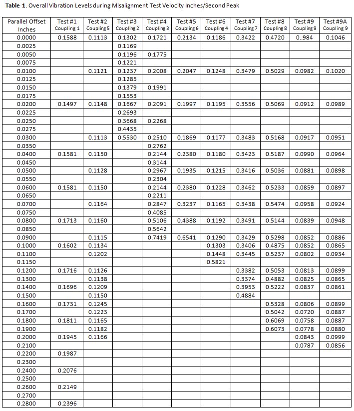
The pump’s overall vibration levels listed in Table 1 were acquired during each coupling test at each of its misalignment increments.
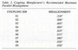
A list of the coupling manufacturer’s recommended maximum parallel misalignment appears in Table 2. This value should not be exceeded in order to maintain the expected life of the coupling. A bar graph is depicted in Figure 2 of the initial overall vibration level for each coupling obtained while the motor was accurately aligned to the pump.
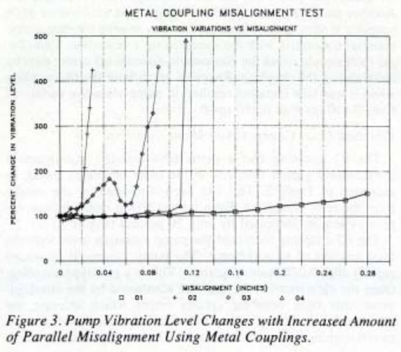
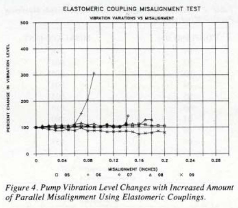
 For ease of comparison, all the vibration levels were normalized using the overall vibration level obtained when the motor was accurately aligned to the pump. The percentage change in vibration level as the misalignment was increased was plotted for each coupling. A graph of the four metal couplings tested is shown in Fig. 3 followed by a graph of the five elastomeric type couplings tested (Fig. 4).
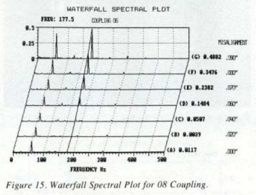
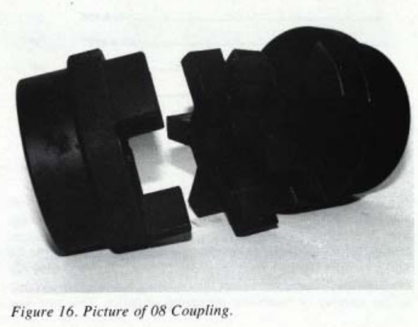
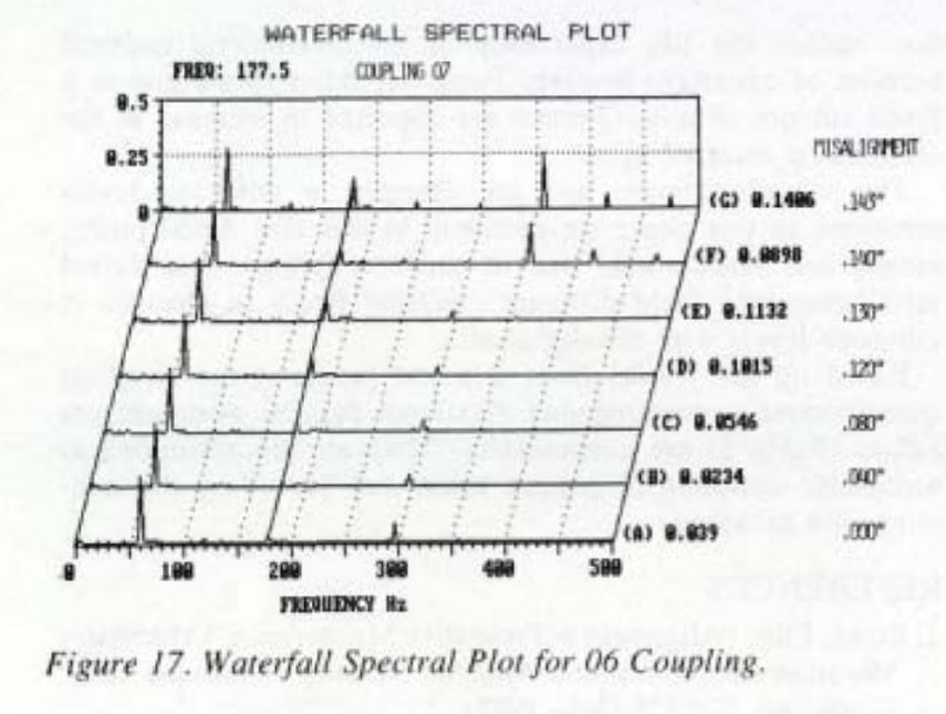
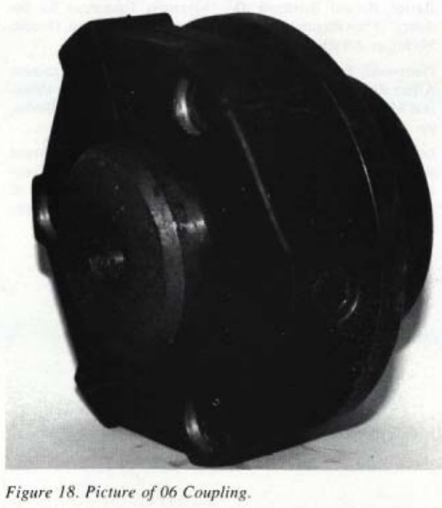
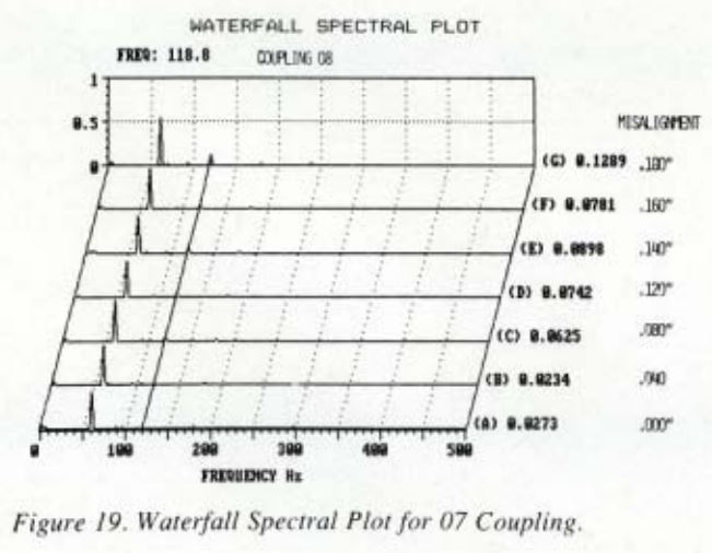
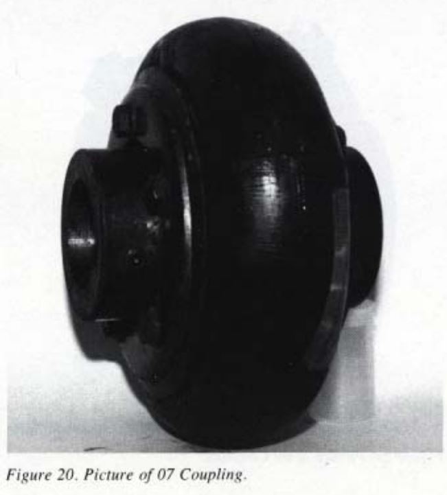
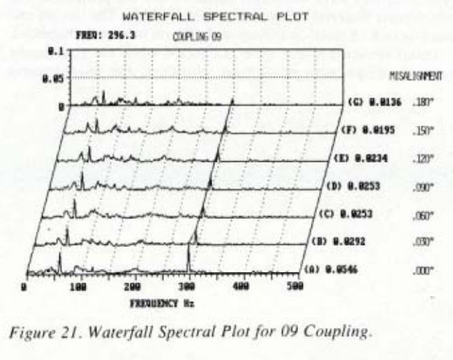
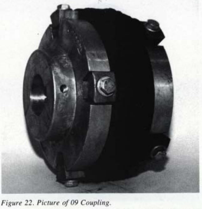
The vibration-amplitude versus frequency-spectrum plots recorded during each coupling misalignment test and the coupling picture are alternately presented in Fig. 5-22.
Discussion of Results
Initial Vibration Levels
The bar graph of the initial pump vibration level for each coupling with accurate alignment is shown in Figure 2. Overall velocity vibration levels greater than 0.157 ips-P are classified as a “slightly rough” running machine per the general machinery vibration severity chart [2]. Vibration levels greater than 0.314 ips-P are classified as a “rough” running machine.
The 06 coupling, during its first installation, caused a pump vibration level of 0.520 ips-P. This coupling was found to be 1.34 in-oz out of balance. The coupling was balanced to less than 0.25 in-oz. The second installation and operation of the pump with this coupling resulted in a pump vibration level of 0.213 ips-P.
When the 07 and 08 couplings were installed, the pump vibration levels classified the pump as a “rough” running machine. It is believed that the high initial pump vibration levels obtained when these two couplings were installed are the result of the coupling being out of balance. Facilities to check and balance these two couplings were not available.
The metal couplings tested generally exhibited a lower initial pump vibration level than the elastomeric type couplings. Two reasonable causes can be cited. As discussed previously, the balance of the coupling is one possible cause. Coupling manufacturers do not dynamically balance each coupling they manufacture. The larger the coupling and the more as cast surfaces, the greater the possibility for the coupling to be out of balance. Another possible cause could be that once an elastomeric style coupling is started, there is no precise way to keep the elastomeric material concentric with the motor/pump’s center line. Centrifugal forces could move the elastomeric material off center thereby unbalancing the coupling. Repeated starts with the 06 coupling when it was first installed resulted in pump vibration variations from 0.450 ips-P to 0.55 ips-P.
Vibration Level Changes with Metal Couplings
The 01 coupling has a permissible parallel misalignment considerably greater than any of the other couplings tested, as indicated in Table 2. This has been supported by the results from the tests conducted. Even with 0.280 in misalignment the pump vibration increased by only 50 percent (Fig. 3).
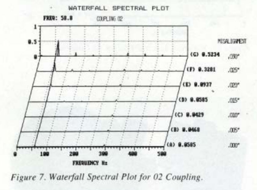
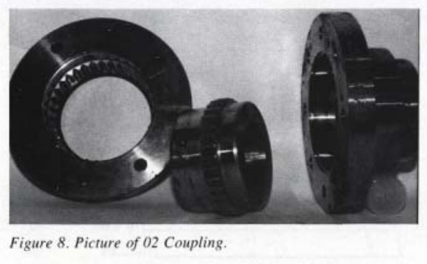
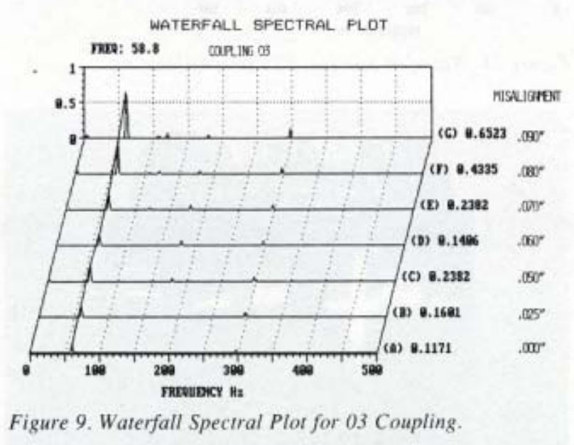
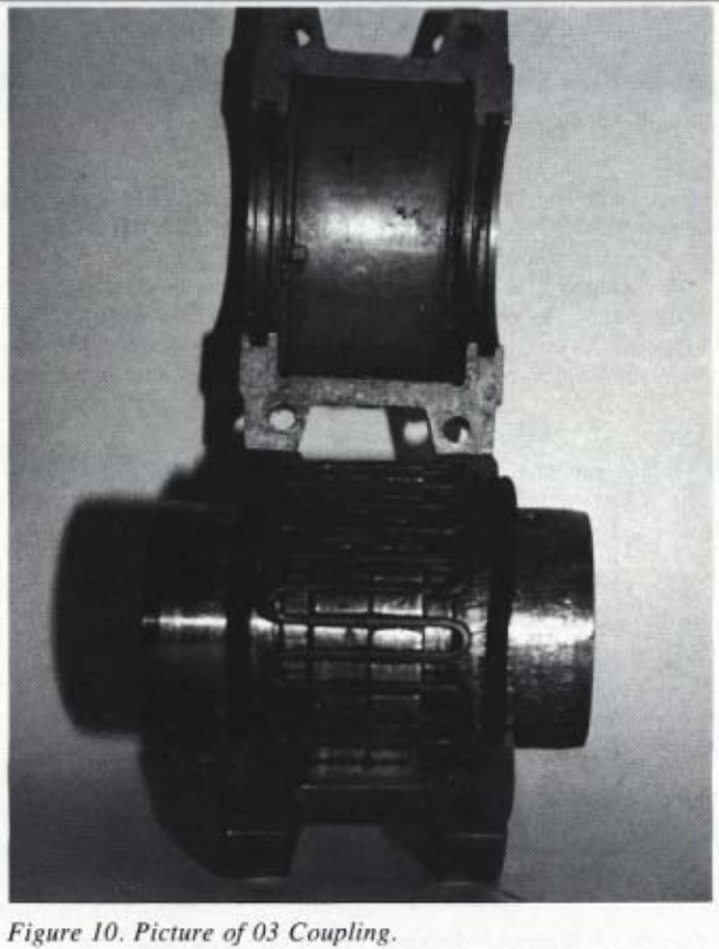
The 02 coupling increased the pump vibration level with the least amount of misalignment. The pump vibrations increased rapidly after 0.020 in misalignment. This is a gear type coupling. Once the clearances in the gear are eliminated by the misalignment, this style coupling creates forces which increase as soon as misalignment occurred when the 03 coupling was tested. An unexpected reduction in the pump vibration occurred when the misalignment was increased through 0.040 to 0.055 in. Pump vibration level increased rapidly with misalignment greater than 0.055 in. The cause of the decrease was discovered upon inspection of the coupling housing halves. Inside the coupling housing halves relative to the spring. During the initial misalignment, the spring was hitting this lug, causing the high pump vibration levels. Once the lug was worn down, the spring was allowed to move, thereby relieving the forces and pump vibration levels.
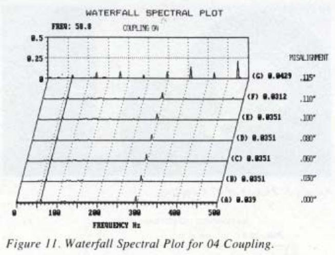
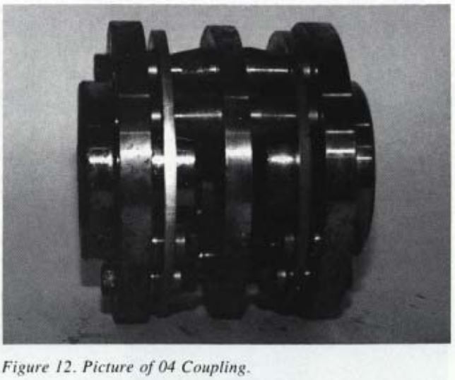
The 04 coupling did not cause pump vibration levels to increase until a mechanical interference occurred on the coupling. The pump vibration increased rapidly (Table 1) at 0.115 in misalignment because its assembly bolts were hitting its hubs. If the assembly bolts were shortened the interference would not exist and the motor could have been misaligned further. However, it was advised that the amount of misalignment already obtained during this test caused deflections which exceeded the material limits of the discs of this coupling.
Vibration Level Changes with Elastomeric Couplings
The results for the elastomeric type couplings are plotted in Fig. 4. Of the elastomeric couplings tested, the 06 coupling caused the pump vibration levels to increase with the least amount of misalignment. The coupling’s elastomeric material inflexibility under compression is the cause of the induced forces which increased the pump vibrations.
The other four elastomeric couplings were able to accommodate a large amount of misalignment without any substantial increase in the pump vibration level. However, these couplings do this at the expense of their life expectancy. The elastomeric material in each of these couplings was hot to the touch after their run test of approximately 30 minutes. Prolonged running of these couplings with this type of misalignment could cause the degradation of the elastomeric material to increasingly become harder and more brittle and begin to create forces that would increase the pump vibrations.
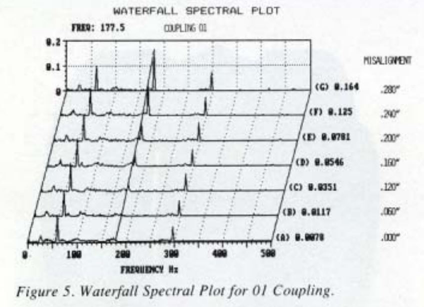
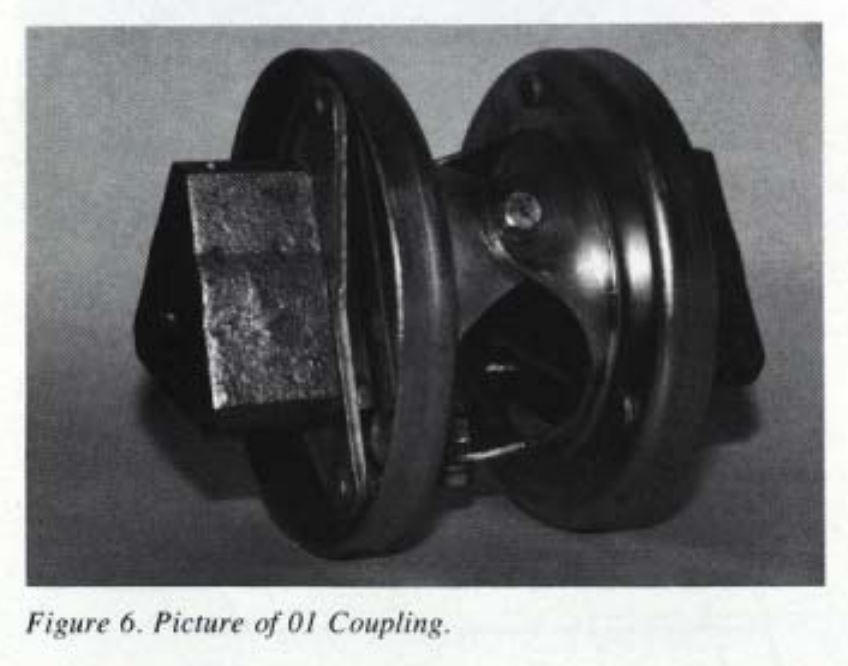
Spectrum Plots
Reviewing the spectrum plots will give some insight into how and why the pump vibration levels change when each coupling was misaligned. The 01 coupling increased the overall pump vibration level due to an increase in vibration at 3x the pump running speed (Fig. 5 and 6). This corresponds to the three flexure beams that make up the coupling. Both the 02 and 03 couplings increased the overall pump vibration level by an increase at 1x pump running speed (Fig. 7, 8, 9 and 10). As mentioned earlier, the 04 caused the pump vibration levels to increase because of a mechanical interference. Its spectrum plots show a sharp increase in all harmonics of the pump running speed when the mechanical interference takes place. This “picket fence” spectrum is typical of either a mechanical looseness or interference (Fig. 11 and 12).
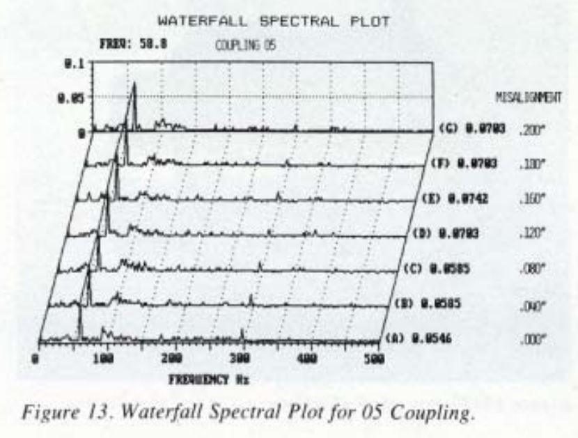
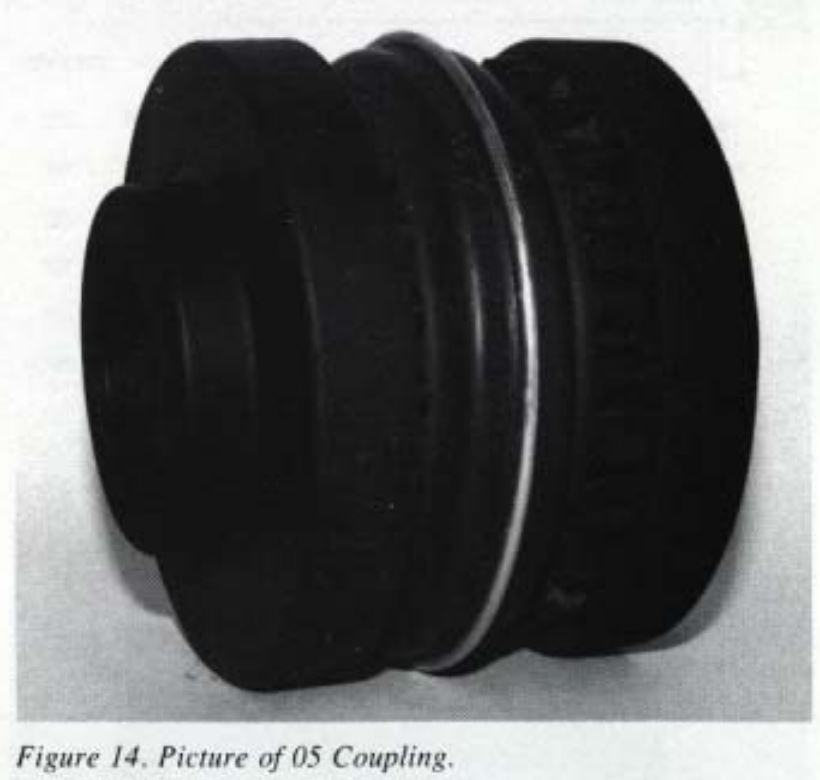
The 05 and 08 couplings had little or no change in their spectrum plots (Fig. 13, 14, 15 and 16). The 06 coupling increased the overall pump vibration levels due to an increase in the vibration at 3x the pump running speed (Fig. 17 and 18). This corresponds to the three-bladed construction of the elastomeric insert of this coupling. The 07 coupling vibration spectrum exhibited amplitude increases at 3x and 6x the pump running speed (Fig. 19 and 20). This was caused by the six-bolt assembly (three bolts on each hub) construction of this coupling. The 09 coupling caused a slight decrease in the pump vibration. Review of its spectrum plots shows small decrease in the 5x pump running speed signal (Fig. 21 and 22). This does not correlate the construction of the coupling but does correspond to the number of vanes on the pump impeller. This test was rerun with the results remaining the same. There does not appear to be a clear explanation to the minor reduction in the 5x pump running speed signal.
A common and accepted vibration analysis fact is that, typically, pump to motor misalignment is indicated by a high vibration level at 1x or 2x the machine running speed. Results from these tests indicated that the type of coupling construction determines the frequency or frequencies that will indicate a misalignment condition. Knowing the construction of the coupling used can assist in vibration spectrum analysis for misalignment. In the case of the elastomeric type coupling, spectrum analysis of vibration may not be a good indicator for misalignment.
Final Remarks
The intent of this presentation is to publish the test results that the author believes are important to the industries that use pumps, motors and couplings. There are no recommendations, direct or implied, of one coupling type or manufacturer over another.
Conclusion and Summary of Results
The elastomeric type couplings induce higher initial-aligned pump vibration levels than do the metal couplings. The elastomeric type couplings have more cast surfaces, and the position of the elastomeric material cannot be accurately held. The design and construction of metal couplings makes them inherently balanced.
Pump vibration levels were unaffected when the elastomeric type couplings were misaligned. However, the misalignment does reduce the life expectancy of the elastomeric material because of excessive heating. Pump vibration levels due to a given amount of misalignment are expected to increase as the elastomeric material ages.
The vibration levels and the changes in vibration levels presented in this paper are pertinent to the size ANSI pump, motor and installation. Use of these couplings in different installations may yield different vibration levels or changes in vibration levels with misalignment.
Based on the results from this test program, the coupling manufacturer’s recommend maximum parallel misalignment values (Table 2) are conservative. They are recommended as acceptable coupling alignment tolerances providing the couplings are balanced.
References
1. Burke, Ellis, “Alignment in Preventive Maintenance,” Machinery Vibration Monitoring and Analysis Meeting, Clarendon Hills, Illinois, pp. 128-128 (June 1982).
2. Baxter, R. and Bernhard, D., “Vibration Tolerances for Industry,” Plant Engineering and Maintenance Conference, Detroit, Michigan, ASME 67-PEM-14 (April 1967).
3. Piotrowski, John D., “How Varying Degrees of Misalignment Affect Rotating Machinery” A Case Study,” Machinery Vibration Monitoring and Analysis Meeting, Clarendon Hills, Illinois, pp. 15-22 (June 1984).
4. Jackson, Charles, “Considerations in Hot and Cold Alignment and Couplings,” Proceedings of the Seventh International Pump Users Symposium, Turbomachinery Laboratory, Department of Mechanical Engineering, Texas A&M University, College Station, Texas, pp. 27-38 (1990).
Copyright 1991. Reprinted with permission of Turbomachinery Laboratory, Department of Mechanical Engineering, Texas A&M University, College Station, Texas 77840-3123.
Source: Goulds