Taco Comfort Solutions offers system design software with interactive tools and video tutorials to help customers’ design an entire LoadMatch system within 30 minutes
VIDEO TUTORIAL INTRODUCTION

What is Taco Hydronic System Solutions?
Taco Hydronic System Solutions is a dynamic, drag-and-drop technology software that assists HVAC designers in the design of hydronic equipment systems, setting of system parameters and the scheduling of HVAC equipment.
Taco Hydronic System Solutions (HVAC systems and their design required)
Although this program includes default values entered at each data input field, a solid fundamental knowledge of HVAC systems and HVAC systems design is required for proper application of the program.
Taco Hydronic System Solutions Project Files
Taco Hydronic System Solutions project files may be saved for reference, shared for review and stored in a library for use on future projects.
Note: When the “Create schedules when saving project” option is enabled, schedule files are automatically created when the project file is saved in the same directory as the project file.
Taco Hydronic System Solutions Work Screen Introduction
The following graphic depicts the basic working screen of Taco Hydronic System Solutions and its features:
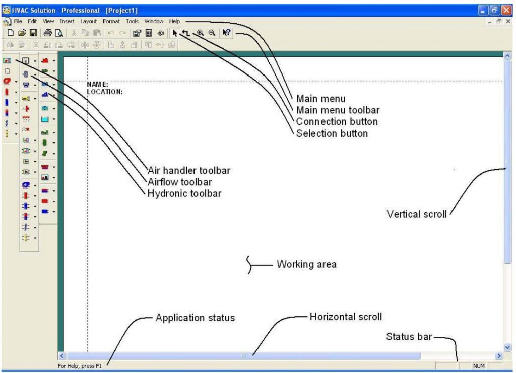
NOTE: The above graphic includes vertical toolbars that are available in the Pro Version of the software. The free version of the Taco Hydronic System Solutions software includes only the features available on the vertical Hydronic Toolbar.
THE BASICS
To begin, basic project creation guidelines should be understood. The basic steps for building a new project include:
Step #1 Component insertion
Step #2 Component arrangement and connection
Step #3 Component parameters input
While the Pro Version of the software allows for the construction of three types of schematics (Air Handler, Air Flow and Hydronic), the Taco Hydronic System Solutions software only allows the construction of Hydronic System Schematics
Note: Duplicate components, components that exist in multiple schematics, automatically appear following an initial insertion. For example, when a coil is inserted into an air handler a duplicate will appear for use in the airflow schematic and a second duplicate will appear for use in the hydronic schematic.
Hydronic Schematic
The hydronic schematic includes wet side components such as pipe, boilers, chillers loads and other components. The hydronic schematic is used to size pipe, calculate pump head, size expansion tanks and other equipment. It is also used to pass information back and forth to the airflow and air handler schematics.
Note: All hydronic components are located in the hydronic toolbar, or the toolbar located by default the furthest right of the left hand part of the screen.
After hydronic components have been inserted, the hydronic schematic should be organized and connected.
Note: Make sure that components are connected out to in or in to out.
GETTING STARTED PICTORIAL
1. Starting a Project
To start a project, click “File” and then “New” under the Main Menu. The workspace will be opened and appear as a white screen.
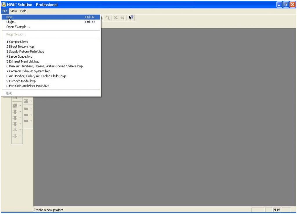
Note: Multiple projects may be opened simultaneously to allow for schematic pieces to be copied from project to project.
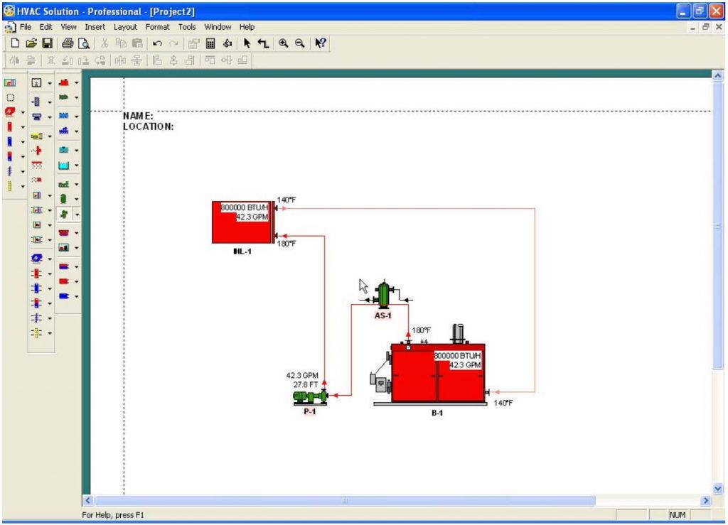
2. Insert an Imposed Heating Load
Insert an imposed heating load by left-clicking its icon located on the hydronic toolbar.
• Drag the component onto the workspace
• Left-click again to drop the component
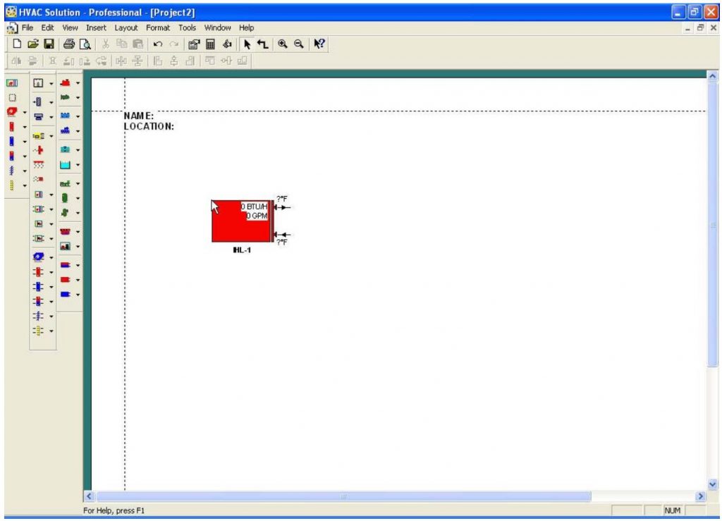
Note: An Imposed Heating Load is a generic load directly imposed onto a hydronic system without the use of an airflow schematic.
3. Insert a Boiler
Insert a boiler by left-clicking the boiler button located on the hydronic toolbar.
• Drag the Boiler onto the workspace and place it relative to the imposed heating load
• Left-click again to drop the component
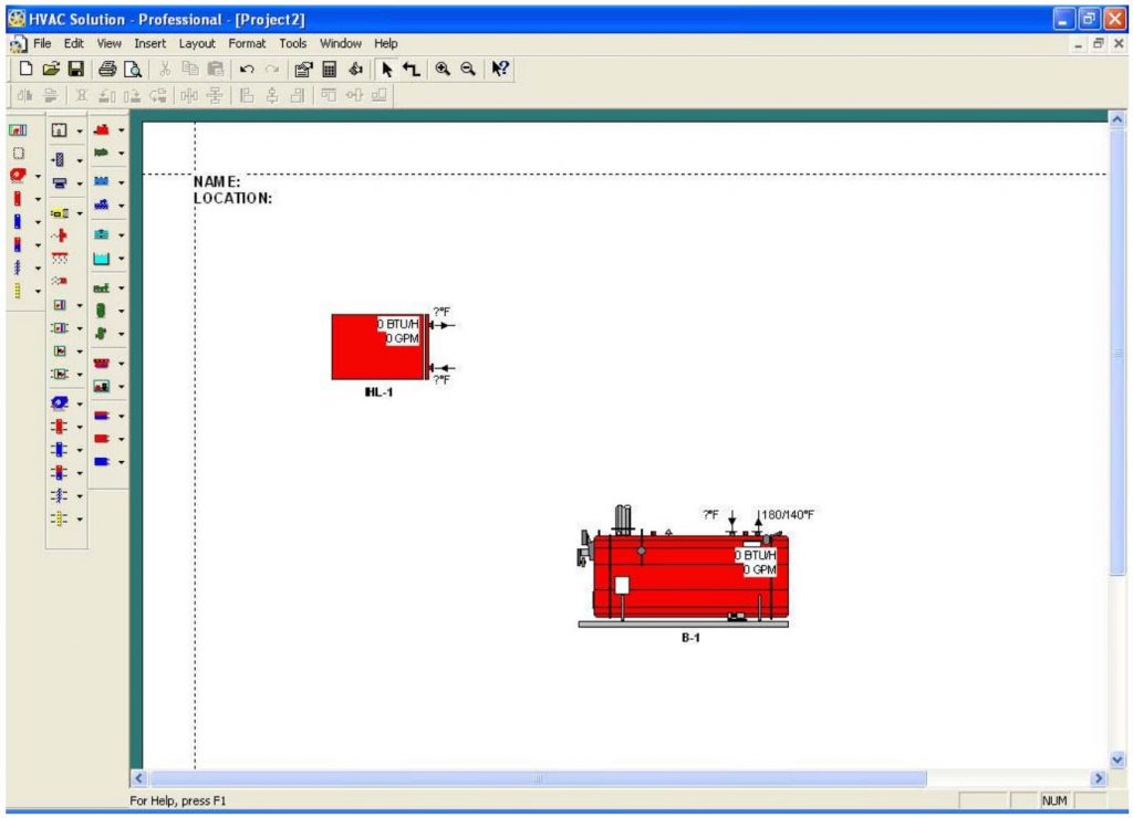
Note: A right-click while in component drag mode will cancel the drag command.
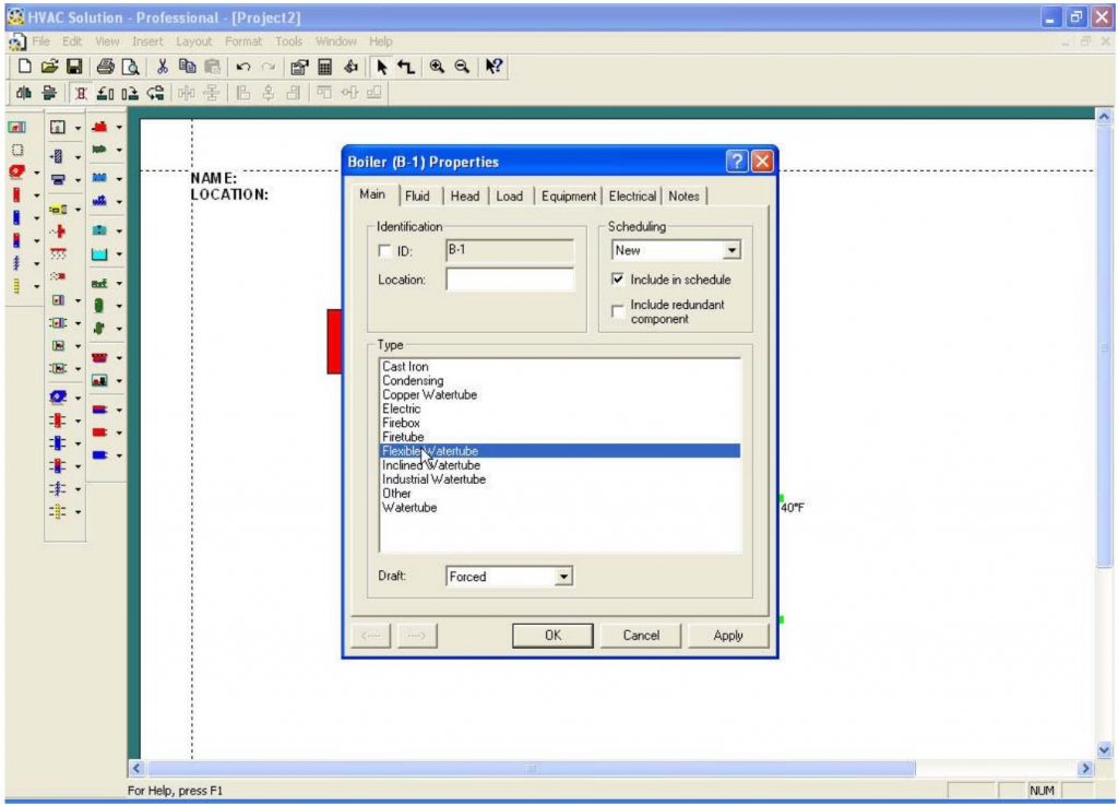
4. Choose the Boiler Type
Equipment type may be changed at any time for any component during the design process. To change the boiler type:
• Double left-click the boiler
• Choose the “Main” tab
• Select a different boiler type
• Click the OK button to continue
5. Connect Components
Once placed on the workspace, components may be connected. The connection icon is the crooked arrow icon located at the top of the screen just below the main menu as shown.
Note: Connections allow components to communicate with each other.
To connect components:
• Click the Connection Icon
• Connect component outlets to inlets
• Left-click on the screen to place pipe bends or elbows
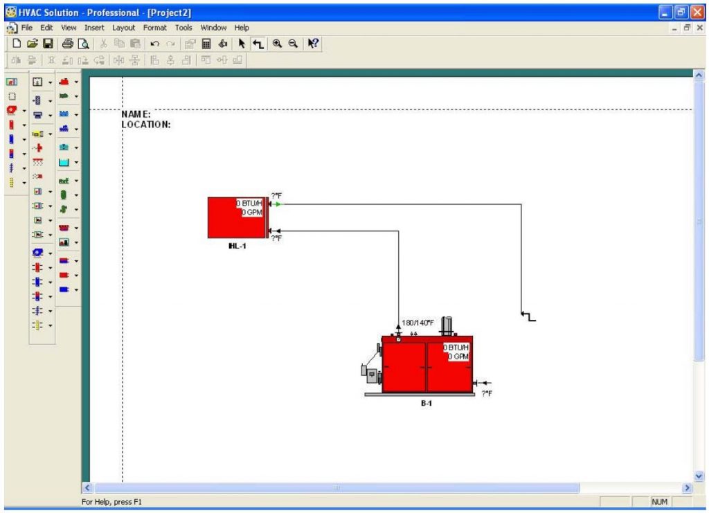
Note: The Taco Hydronic System Solutions Software defaults to the LoadMatch® Design. The LoadMatch® Design will insert a Circulator and a bypass in the imposed load connections to facilitate the single pipe design. The LoadMatch® Design feature can be turned off to allow the design of non-LoadMatch® Systems by clicking on Edit and then unchecking The Taco LoadMatch® Design option.
6. Insert a Pump
To insert a pump:
• Left-click the pump button located on the hydronic toolbar and drag pump onto the screen
• Left-click the mouse button once the pump is positioned over the top of a pipe. The pump automatically inserts itself into the pipe
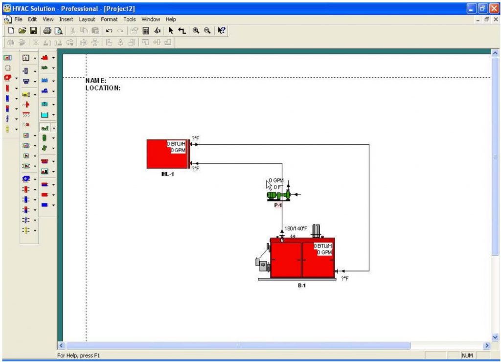
Note: To drag the pump into position after it is inserted, left-click it and drag as desired.
7. Editing Imposed Heating Load Properties Dialog
To Edit:
• Double left-click on the imposed heating load and choose the “Load” tab
• Enter a load in the heating season field
• Click the OK button to continue
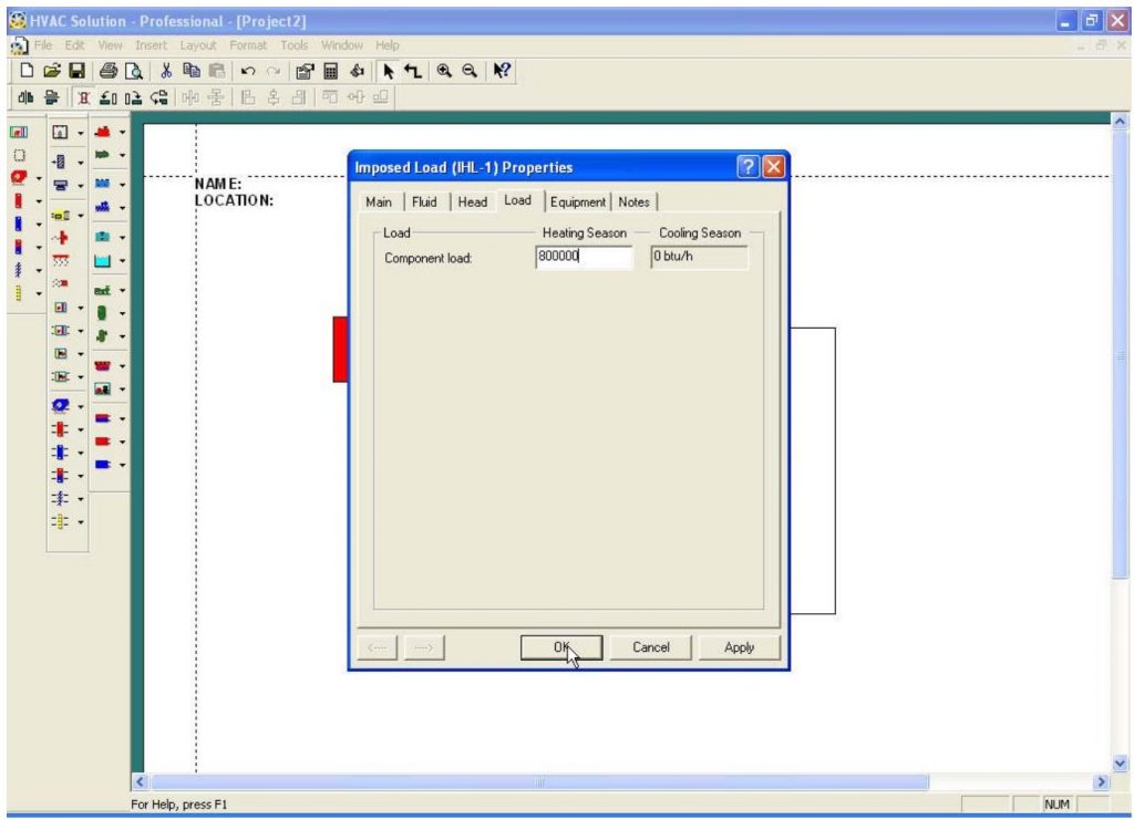
Note: Once a load is entered and a circuit is made complete, relevant information is communicated to other components. The pump will insert properly if it is placed on a single pipe only (not spanning two pipes).
8. Adding Length to the Pipe
To add length:
• Double left-click on a pipe
• Choose the “Main” tab and enter a pipe length
• Click the OK button to continue
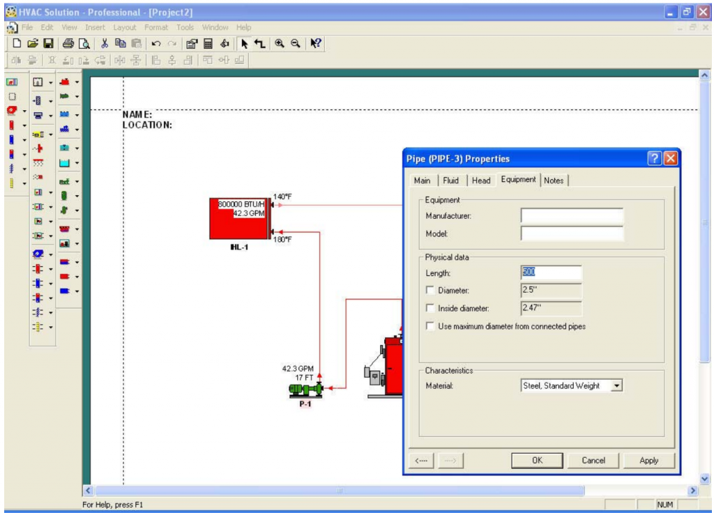
Note: Entering pipe length adds head to the pump and volume to the expansion tank.
9. Inserting an Air Separator
To insert an air separator:
• Left-click the air separator icon located on the hydronic toolbar
• Drag the air separator onto the workspace and position it on top of a pipe
• Left-click again for automatic insertion
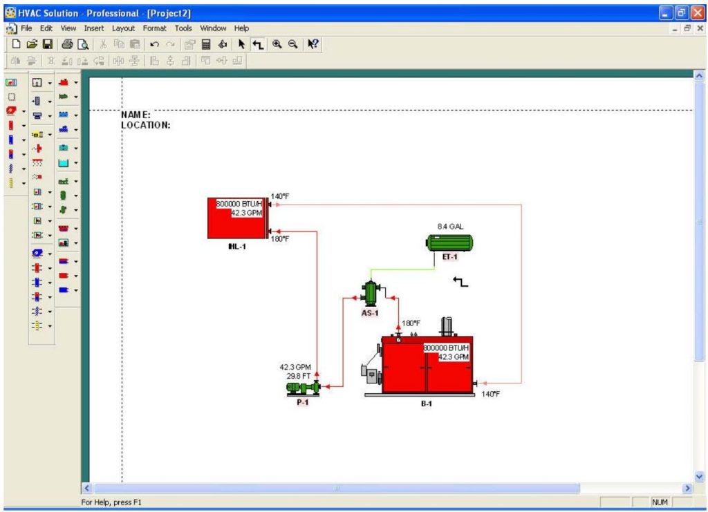
10. Inserting an Expansion Tank
To insert an expansion tank:
• Click the expansion tank on the hydronic toolbar
• Drag it onto the workspace
• Connect it to the air separator
11. Save the Project
To save the project:
• Click “File” from the Main Menu and “Save As”
• Choose a file location and name
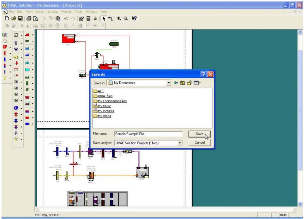
Note: In the following example the file name “Sample Example File” will be used.
12. Connecting Hydronic Parts
To connect hydronic parts:
• Move the heating components (HC-1 and TBG-1) near the Imposed Heating load (IHL-1)
• Connect them to the existing schematic

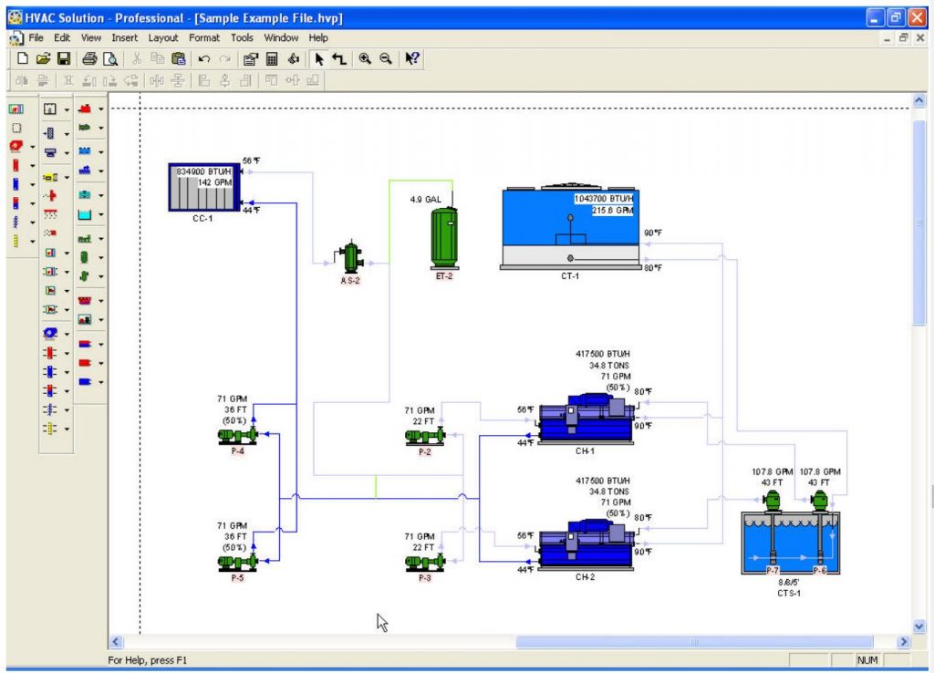
13. Inserting a Chiller Schematic
To insert a chiller system similar to step 11 using parts from the example library:
• Select “File” from the Main Menu bar and “Open Example”
• Choose “Hydronic Systems”
• Open the “Water-Cooled Chiller Duplex Primary Secondary .hvp” file
• Select all objects to be copied by left-clicking the screen below and right of the objects while holding the left mouse button down, drag the mouse to the upper left corner of the objects
• Release the left mouse button. All objects to be copied will be highlighted
• Select “Edit” and “Copy” from the Main Menu
• Select “Window” from the Main Menu
• Open the “Sample Example” window
• Paste the objects into the file
• Position the new schematic as desired by left-clicking one of the highlighted components
• Connect the coil, (CC-1) into the existing schematic
• Delete the extra imposed cooling loads, (ICL-1 and ICL-2)
Note: Be sure to connect CC-1 prior to deleting ICL-1 and ICL-2 to maintain the existing piping configuration.
14. Changing Chilled Water Properties
Edit the leaving chilled water temperature by:
• Double-clicking the cooling coil
• Choose the “Fluid” tab
• Change the leaving fluid temperature during cooling season
Note: Chillers provide cooling. Enter data to be handled by the chiller in the cooling season field. Information entered in the chillers heating season field represents cooling done during the heating season. Normally, temperatures are entered in seasons relevant to equipment and are left alone in fields that are not relevant to equipment.
15. View pump head
• Double-click on a pump
• Choose the “Head Summary” tab to view the head summary for that pump
• Uncheck the box entitled “Show only nonzero values” to view all objects detected by the pump
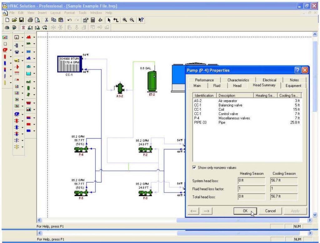
Note: If necessary, return to components and edit individual head information located in the “Head” tab of each component.
16. Insert Pipe Size
Display pipe size annotations:
• Window select all piping
• Single right-click on a selected object
• Choose pipe in the sub-selection list and push OK
• Choose “Annotation”, then “Pipe”
• Select “Diameter” from the drop down “Annotation description” list
• Press OK
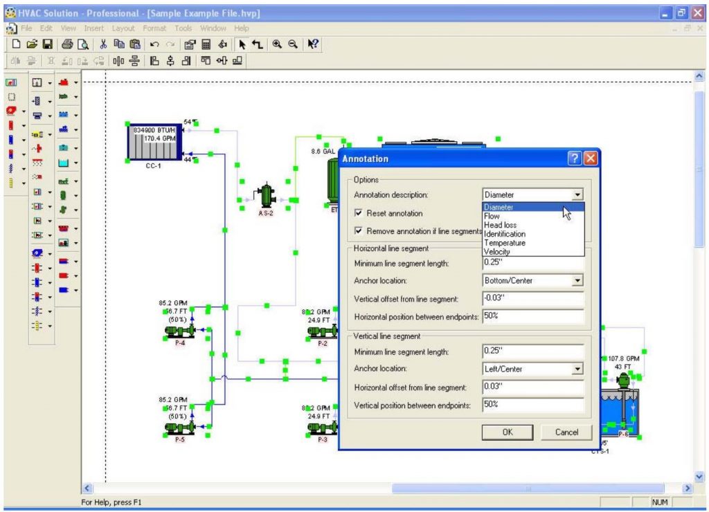
Note: To insert multiple annotations on a single drawing it is necessary to offset subsequent annotations. This is done by changing the anchor location, the vertical offset or the horizontal position as described in the “Annotation” dialog.
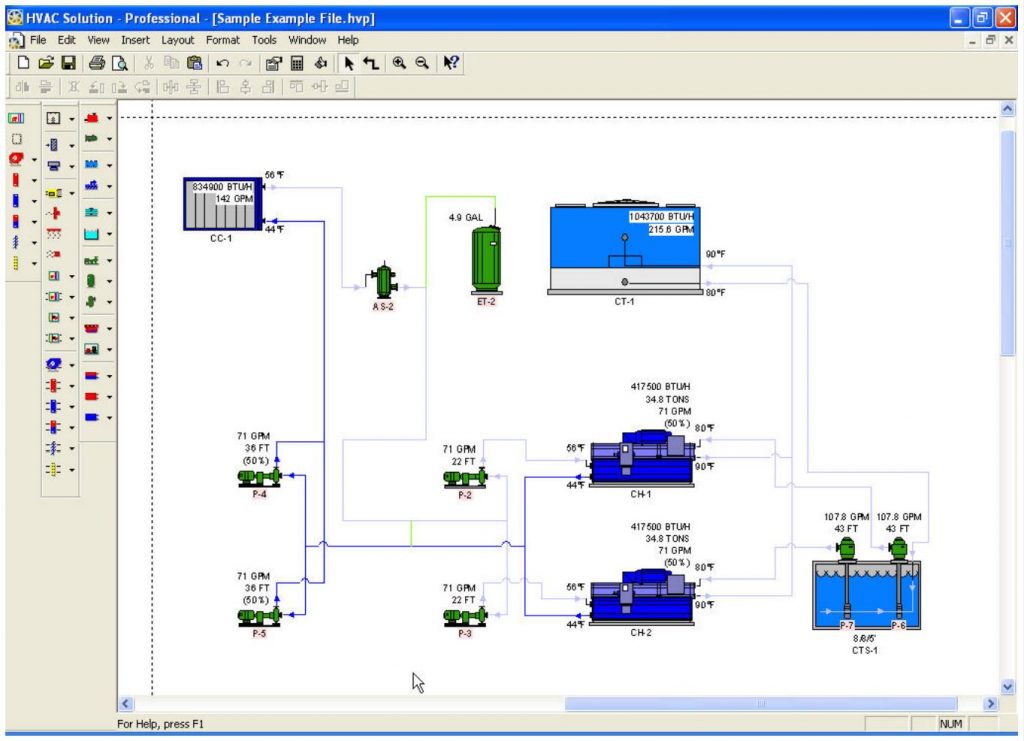
17. Selecting Equipment
As equipment is inserted on the schematic, any equipment that is automatically selectable will be designated with labels that are highlighted in pink (red for stop). The equipment can be automatically selected using the “thumbs-up” icon on the Main Menu Toolbar or by opening the particular component’s properties box and going to the Equipment portion of the Properties. Once equipment has been selected, the highlighting will go away indicating that valid selections have been made. All selections can be over-ridden by the user.
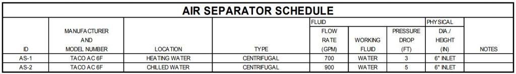
18. Saving Schedules
The final output from Taco Hydronic System Solutions is document ready schedules. Schedules can be placed directly onto construction documents.
To save:
• Click “File” from the Main Menu and “Schedule Options”
• Check the “Create schedules when saving project” in the top part of the dialog
• Check one of the schedule types to be saved
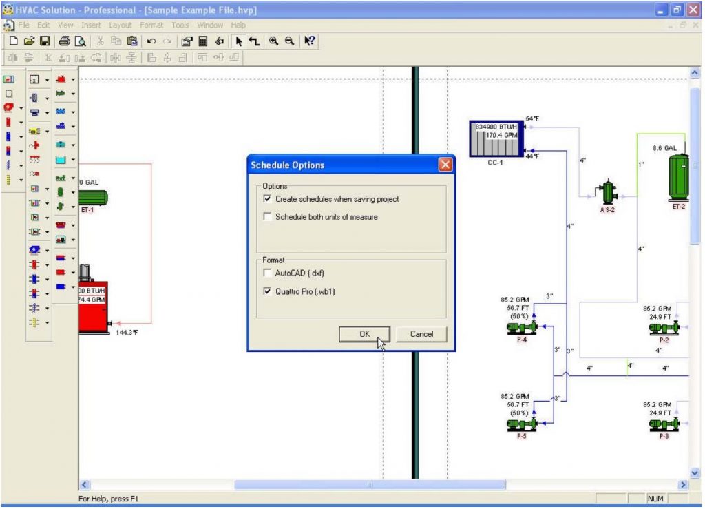
Note: Schedule files are saved in the same location as the project files.
The following is an example of an equipment schedule produced by Taco Hydronic System Solutions (wb1 – spreadsheet and dxf – CAD formats):
TIPS
Annotation Tips
Insert a bunch of pipe or duct sizes at the same time
• Select a group of pipes or ducts
• Choose “Insert” from the main menu
• Choose “Annotations”
• Choose “Pipe” or “Duct”
Connector annotations – lost
• If the annotation offset and position equals previous offset and position values, the annotations will be stacked on top of each other
• If an annotation cannot be viewed they may be moved one at a time or re-inserted by changing the offset or position value
Annotations – display order
• Heating season annotations are always displayed first – top to bottom and left to right
• Cooling season annotations always displayed second – top to bottom and left to right
Duplicate Schematic Components
Duplicate components – defined
The three basic schematic types are Air Handler, Airflow and Hydronic. Duplicate are components are components that appear in two or more schematics. For example, when a coil is inserted in an air handler a duplicate component will appear for the airflow schematic, likewise for the hydronic schematic. Duplicate components guidelines include:
• Airflow and hydronic components may be set aside for later connection
• Airflow schematic components always peel off first, then hydronic components
• Air handler components always have duplicate airflow schematic components
• All coils have duplicate hydronic components
Duplicate components – re-inserting
• Right-click the component and select “Duplicate Schematic Component”
• A duplicate component may only be inserted if it does not already exist in the schematic
Duplicate components – cancel insertion
• Right-click to cancel the automatic insertion of a duplicate component
Colored Connectors
A correct connection (pipe or duct) is made when:
• The outlet of one component is connected to the inlet of another
• A flow rate is established
• The system is reasonably complete
Once complete:
• Connectors automatically become colored.
Generally connectors follow the following rules:
• A system is usually correct if pipes are a solid color (except for black)
• Dashed pipe = incorrect
• Black pipe = incorrect
Fluid Temperature – Which One Do I Enter?
Generally, the default fluid temperature values and settings are your best choice. By default fluid temperatures are set based on the rules:
• Leaving fluid temperature is set at generation components
• Temperature change (delta T) is set at consumption components
I want to override default fluid conditions:
• Don’t override the default fluid setting (entering or delta T) unless you know what you are doing!
Components defaulted with a leaving fluid temperature:
• Boilers
• Air Cooled Chillers
• Cooling Towers
• Heat Source-Sink
Component defaulted with a temperature change (delta T):
• Imposed Loads
• Terminal Boxes
• Unit Heaters
• Panel Radiators
• Finned Radiators
• Fan Coils
• Fluid-to-Air Heat Pumps
• Coils
Components defaulted with a leaving fluid temperature (generation side) and a temperature change (consumption side):
• Heat Exchangers
• Water Cooled Chillers
• Fluid-to-Fluid Heat Pumps
Go with the Flow
Components generally should be arranged so that a schematic may be built by:
• Working left to right, top to bottom (instead of flipping)
• Grouping similar components for later connection
Heating Season vs. Cooling Season
Two seasonal maximums are allowed for which equipment is sized to include the heating and cooling seasons.
• For heating only projects, fill in “Heating Season” information
• For cooling only projects, fill in “Cooling Season” information
Leave information pertaining to an unused season blank or at the default setting if that season is not to be used.
HELP TIPS
Where can I get help?
• Data fields (input and output) – Left-click the “?” in the top right hand corner of any properties dialog then click the curser on a data field
• Topic – Left-click the main menu, “Help”
• Email – taconet@taco-hvac.com, be sure to describe your question and attach your project file
• Call – 800-441-1969 (Monday through Friday Eastern Standard Time)
Keeping Your Schematic Clean Tips
Positioning toolbar
• Select a group of components to be aligned and then press an alignment button
Straightening pipes or ducts
• Left-click and then window select a group of pipes or ducts to be straightened
• Repeat this action until the group is aligned
• It may be necessary to move some pipes/ducts closer to the main trunk for the straightening action to occur
Multiple component editing
• Left-click and then window select multiple items
• Double left-click on of the selected items
• Access the multiple editing feature
Keyboard shortcuts
• Ctrl-A – select all
• Ctrl-X – cut
• Ctrl-C – copy
• Ctrl-V – paste
• Ctrl-Page Down or Ctrl-Tab – scrolls left to right through dialog box tabs
• Ctrl-Page Up Shift-Ctrl-Tab – scrolls right to left through dialog box tabs
LoadMatch® Tips
Check the Taco LoadMatch® Design option
• Make sure the Taco LoadMatch® Design option is checked under “Edit” of the main menu
Ensure the correct flow direction for the main loop
• Outlet of generation components to inlet of load first
Enter loads
• Calculations will not happen until a loads value is set (note the color change)
Set generation entering/leaving temperature
• To force a main loop flow set the entering/leaving temperature at the generation component (e.g. boiler)
Set the delta T at each load
• Each load should have a delta T set
Set the entering and leaving temperature
• Set both the entering and leaving temperature at the generation component to force a minimum flow through the main system loop
Mouse Tips
Connection vs. Selection
• Selection mode is default
• Use the crooked arrow in the main menu for connecting
• Right-click the mouse to cancel connection mode
Left-click
• Drawing operations
Right-click
• Editing operations
Putting equipment on the screen (clicking an icon)
• Left-click the icon and release, do not drag
How to connect to an inlet/outlet (connection point)
• Outlets connect to inlets
• Left-click the arrow
Putting a pipe where you want it (elbows)
• Left-click the screen
Properties Dialogs
Equipment (component) properties dialog – opening
• Double left-click the mouse on a component to directly open its properties dialog.
Project properties dialog – opening
• Single left-click on the white workspace to clear any selection and then double left-click the white workspace to open the project properties dialog.
Getting used to the layout of properties dialogs – component similarity
Most components (equipment) are similar and therefore becoming familiar with one will also familiarize user with others.
• Most components have similar functions and tabs
• Once you know one, you know many
Grayed-out data
• Fields displayed as grayed out represent data that the program automatically calculates or fills in. The user can edit only data that is displayed in white fields.
Standard Windows Commands
This program employs standard Windows commands:
• Cut, copy and paste within this program
• Entities may be pasted directly into other Windows compatible programs
Straightening Pipes and Ducts
Left-click, window select the pipes/ducts to be straightened, left-click again, repeat until straight
The pipes/ducts must be reasonably close for this action to occur
Tips
• Tips are included for quick reference only
• For detailed topic information see each individual topic
Toolbars vs. Menu Design
• Components may be inserted by using either the toolbar or the main menu
• The toolbar uses buttons for a graphical interface
• The main menu uses text
“Why should I use this program?” Tips
Time savings
• Re-use old projects
• Use pre-built projects
• Easy last minute design changes
Increased accuracy
• Easily review-able by multiple eyes
Improved documentation
• Centrally stored project calculations
• Quick reference for reference of design decisions
Professional marketing efforts
• Descriptive graphics that can be understood by everyone
Design standardization
• Set office standards by setting project defaults
Clear communication of design intent
• Design parameters are included within project files for clear communication of design intent
Run different design scenarios
• Layout and compare systems
It’s fun to use!