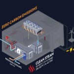
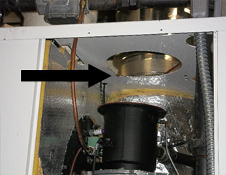
Since the launch of the CFLC 4000/5000 boilers, Cleaver-Brooks has noticed issues with the rain and recirculating flue gases collecting in the air intake over the motors
In some cases, the current motor seals are allowing water to go into the motor.
The root cause of many of these problems is improper combustion air and/or flue venting arrangements. This can include improper air intakes, improper flue terminations; combined venting without isolation dampers, air intakes in too close of proximity flue gas terminations and too small air intakes; in some cases, more than one of these is present. When this is the case, the problem in the venting configuration should be addressed.
In instances where the venting configuration cannot be changed, Cleaver-Brooks has developed a design modification in the blower and venturi intake system to help deal with these adverse situations. This has recently been implemented into production of CFLC-4000 & -5000 for 460V power applications. Following is an upgrade option available for existing CFLC-4000 & -5000 installations with 460V power.
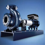
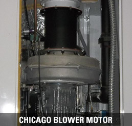
Changing the current Chicago Blower blower-motor to an ECM gas premix blower-motor.
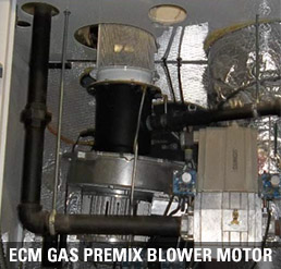
Also incorporated with the blower change is an offset for the fan to a 5° angle, thereby preventing water from collecting over the motor shaft seal.
Removal of Chicago Blower Instructions
 Remove the following parts:
- Sensing line (save to reuse)
- Air filter (save to reuse)
- Piping and gas train to help create clearance (save to reuse)
- Venturi (save nipple w/ orifice to reuse)
- Aluminum tubing (save to reuse)
- Falcon controller
- Pilot tube-(save to reuse)
- VSD & all associated wiring
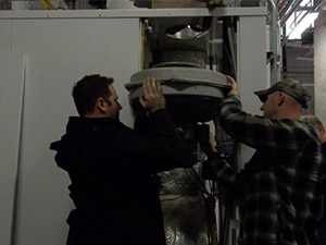
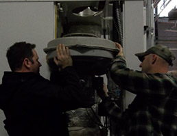
When removing the blower motor you may need a come-a-long or two technicians.
- Remove swivel bar (pound pin upward)
- Remove burner-mounting plate
Installation Instructions of New ECM Blower
Install the following parts:
- New Falcon Controller (833-04086-000. See instructions at end of bulletin for wiring changes)
- New Gasket & Burner Plate
- Aluminum tubing
- Prepping Blower
- Install power and signal cable plugs
- Install new hardware on venture
Continue installing the following:
- Mount Blower with new gasket (mounts to burner plate with 5/16-18 nuts and washers) Venturi and new venturi gasket (mounts to blower with supplied M8 x 20mm hex head cap screws)
- Gas Nipple with union half to venturi
- Connect back the gas train (will need to angle to line up to new venturi)
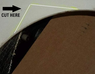
- You will need to cut a wider opening for Air filter (cover venturi so shavings do not enter)
Continue installing:
- Gasket & Air Filter
- Igniter Cable
- Sensing Line (will need to bend to fit properly or cut an inch shorter)
Wiring Changes:
- Remove all of the wires going to the VSD
- Remove wires going from terminals 21 and 22 to VSD
- Remove wires (41 and 42) going from VSD to Falcon plug J10-4 andJ10-6
- Remove wires from VSD to terminals 5, 39, and 40
- Remove 3-phase power from VSD to fuse holders
- Remove wire cable going to CAPS switch and wirenut each exposed wire
- Remove wire going from terminal 12 to Falcon terminal J7-3
- Run new wire from terminal 8 to CAPS switch COM terminal
- Move wire on Falcon terminal J7-4 to J7-3
- Move wire on Falcon terminal J7-5 to J7-4
- Move wire on Falcon terminal J7-6 to J7-5
- Move wire on Falcon terminal J6-1 to J7-6
- Move wire on Falcon terminal J6-2 to J7-7
- Run new wire from Falcon Terminal J6-2 to CAPS switch N.O. terminal
- Wire Blower motor power cable to fuse blocks and ground terminal
- Route blower signal cable through empty panel hole and insert into Falcon plug J2
- Hook up signal and power cables to plugs attached to blower motor
If you are interested in obtaining a blower motor upgrade, please contact R.F. MacDonald Co. at 510-784-0110 or email us at info@rfmacdonald.com.